G3 Series EtherCAT
TM
Technical Manual
7-55
Subject to change without notice
www.asco.com/g3
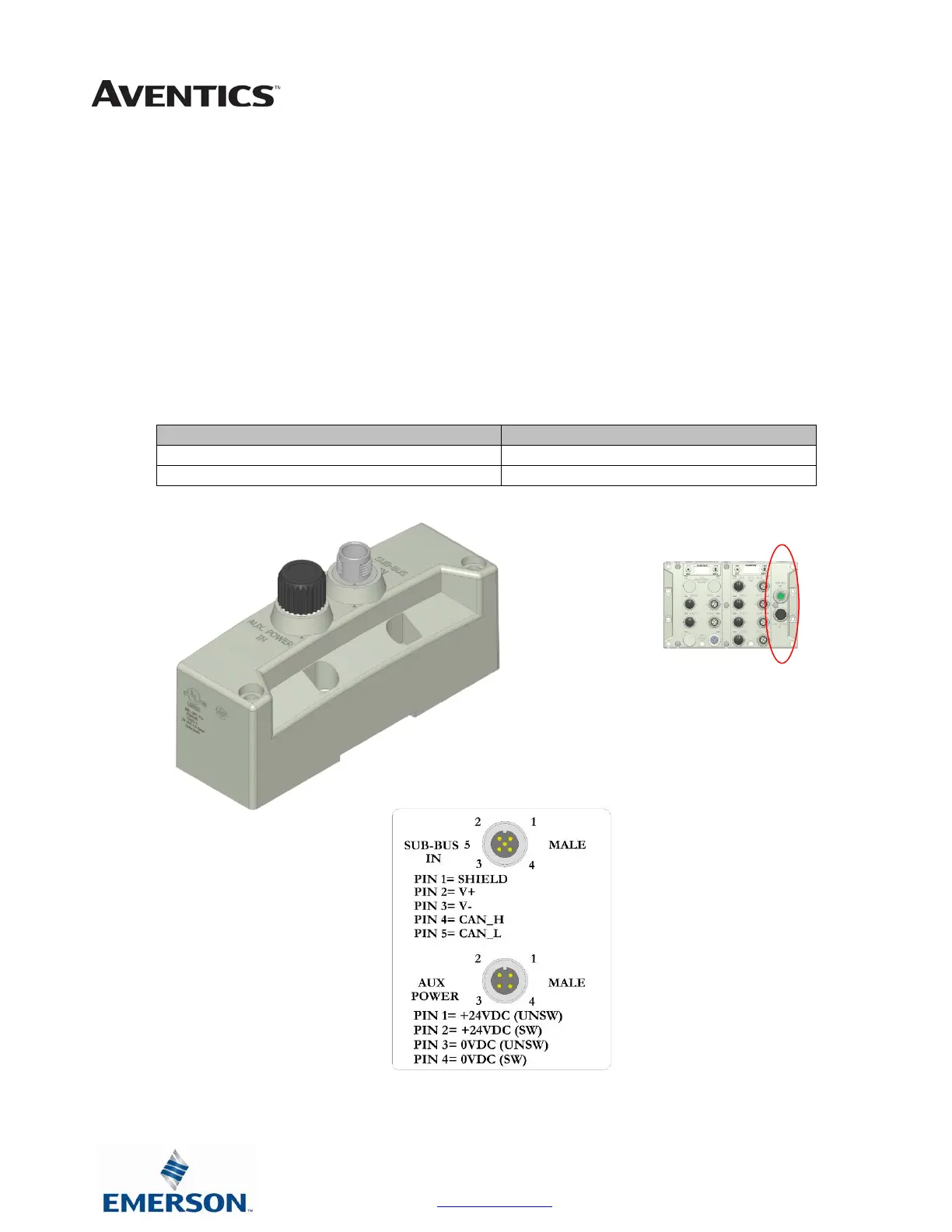
SUB-BUS IN Modules
•
Used to distribute I/O assemblies that do not have valves
o Must be installed to the right of the I/O modules.
4. SUB-BUS IN - 5 pin M12 male communication connector.
o Must be connected to the Sub-Bus Out connector of the previous assembly
o Carries 24 VDC power for electronics of module
5. AUX. POWER IN - 4 pin M12 male connector.
o Aux power is required for Output modules. This connection also allows Output power to be interrupted to
all Output modules connected to this module.
o Aux. Power is optional for Inputs. Power from the SUN-BUS IN connection is used to power
sensors but can be augmented, if necessary, by adding additional power to this connector.
Description Part Number
Sub-Bus IN module with Din Rail Mounting 240-246
Sub-Bus IN module without Din Rail Mounting 240-185
 Loading...


