G3 Series EtherCAT
TM
Technical Manual
7-57
Subject to change without notice
www.asco.com/g3
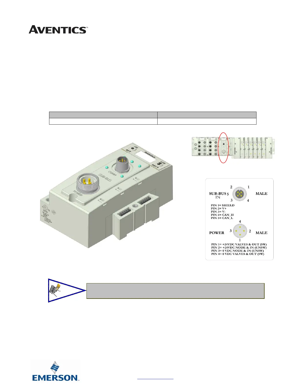
G3 Sub-Bus Valve Module
7. COMM - 5 pin M12 male Sub-Bus input communication connector.
o Must be connected to the SUB-BUS OUT connector of the previous assembly
o Carries 24 VDC power for electronics of module
8. POWER - 4 pin MINI male power connector.
o Power is required for Outputs
9. Used to distribute Valves on the Sub-Bus.
o Can accepts discrete I/O module to allow a Sub-Bus Valve manifold with I/O
Description Part Number
Sub-Bus Valve Module 240-241
• There is a 0.8 VDC drop in power across this module, consider this when
distributing Aux. power.
 Loading...


