Safety
information
Product
information
Mechanical
installation
Electrical
installation
Getting
started
User Menu A
Commissioning
Advanced
Parameters
Diagnostics Optimization CT MODBUS RTU Technical Data
160 E300 Design Guide
Issue Number: 1
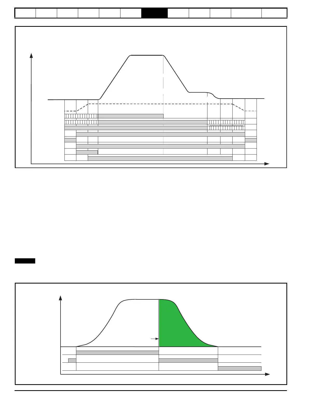
Figure 7-4 Creep to floor profile, Timing diagram
7.6 Direct to floor profile
For some applications, especially high-speed elevators and long travel distance elevators, direct-to-floor positioning control is often used to overcome
inherent delays associated with creep-to-floor elevators.
Direct-to-floor positioning alone should only be used on elevators up to 1 m/s due to the accuracy and sampling of the E300 Advanced Elevator drive,
above 1 m/s floor sensor correction should be enabled in addition.
The acceleration rate and all jerk rates of the velocity profile are independently adjustable, enabling the performance of Direct to floor operation to be
optimized. The relevant parameters are as shown in Figure 7-5.
The deceleration profile in Direct to floor operation is applied according to the slowing distance to the selected floor level. The elevator controller
instructs the drive to slow, either by applying a stop signal to digital input 4, or by deselecting the speed signals. This takes place at a distance from
the selected floor level, which matches the slowing distance achievable with the required deceleration rate from the selected speed. On detecting the
stop signal the drive decelerates directly under position control into the floor level. Creep speed positioning is not executed nor required.
The E300 Advanced Elevator drive calculates the deceleration distance for each of the speed references taking into account the profile settings.
Alternatively the user may specify a distance for each speed. The relevant parameters are shown in Table 7-12. The actual distance is displayed in
Deceleration Distance Measured (J44).
If either the slowing signal is given too close to the selected floor level, or the user deceleration distance is too short for the selected speed, it is
possible that the car will stop too late and hence overshoot the floor level.
Figure 7-5 Velocity profile with Direct to floor positioning
Drive active
Direction
FAST disable
STO, Drive enable
Creep Speed
Start lock
Speed selection
Torque producing current
Debounce motor contac
tors (100 ms)
Brake Control Apply Delay ( )D05
Interlock delay (> 50 ms)
Control terminal 26
Run Jerk 1 ()G13
Run Jerk 2 ()G14
V2 Speed Reference ()G02
V3 ()G03Speed Reference
V3 ()G04Speed Reference
Ramp torque (100 ms)
Ramp torque (100 ms)
Control terminal 7 (V2), 26 (V3), 5 (V4)
Control terminal 29
Control terminal 28
Control terminal 31
Drive active, L06
Brake output
Control terminal 25
Start lock position Kp, 120
External motor contactor control
External motor contactor control
Run Jerk 3 ()G15
Brake Control Release Delay ()D04
Acceleration Rate
()G11
Deceleration Rate
()G12
Run Jerk 4 ()G16
Creep Stop
Deceleration Rate ()G17
V1 Creep Speed Reference ()G01
Creep Stop Jerk ()G18
Brake Control Apply Delay ()D05
Speed signals
Stop signal**
Level sensor
** Only if direct-to-floor positioning with stop signal
Run Jerk 1 ( )G13
Acceleration
Rate ( )G11
Run Jerk 2 ( )G14
Operational speeds
(to)G01 G10
Run Jerk 3 ( )G15
Deceleration Rate ( )G12
Run Jerk 4 ( )G16
Deceleration Distance
Calculated ( )J43

 Loading...
