Safety
information
Product
information
Mechanical
installation
Electrical
installation
Getting
started
User Menu A Commissioning
Advanced
Parameters
Diagnostics Optimization CT MODBUS RTU Technical Data
80 E300 Design Guide
Issue Number: 1
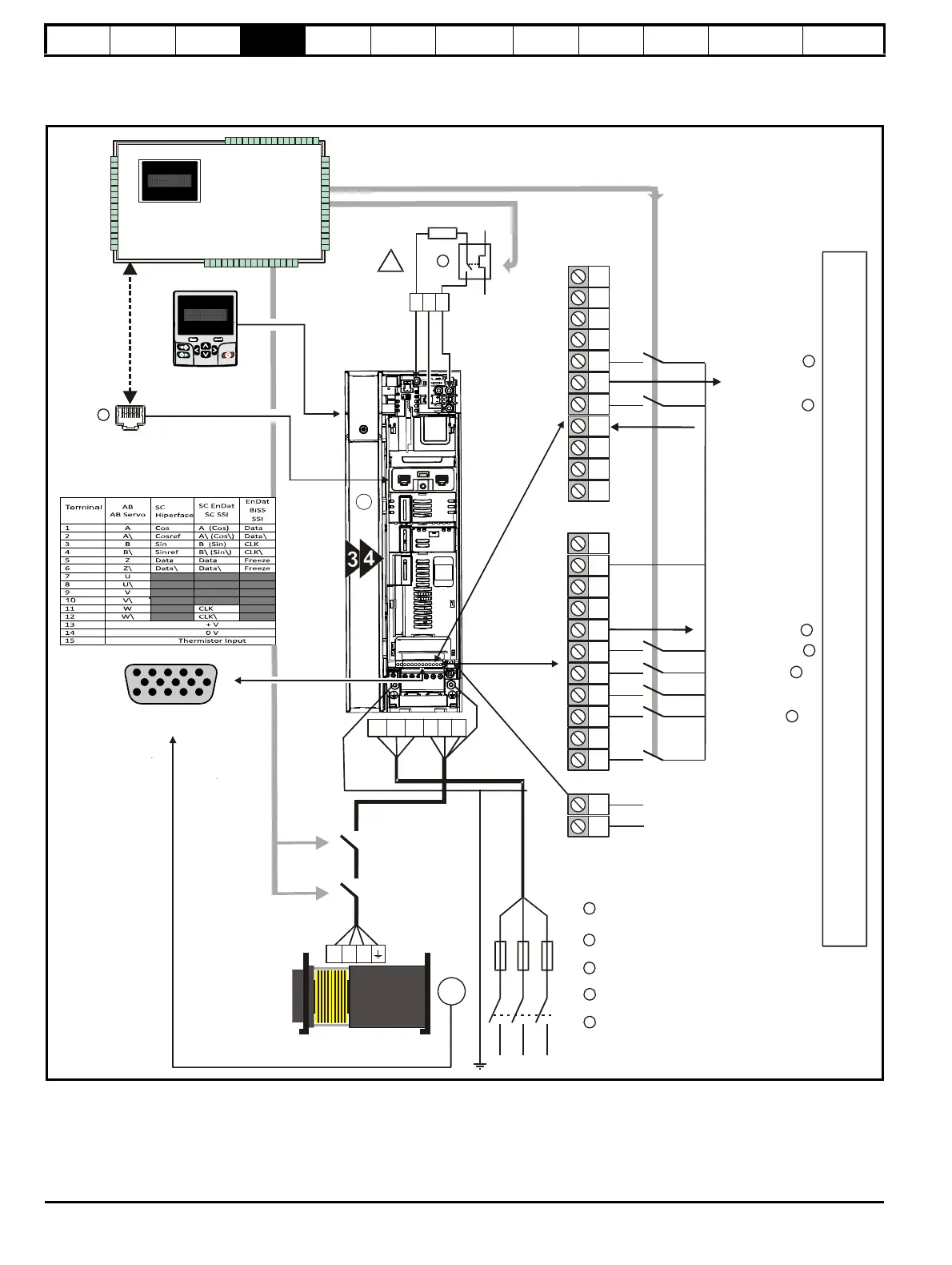
4.8 Minimum connections
This following section shows the basic connections which are required for the drive to operate.
Figure 4-16 Minimum connections for operation in RFC-S mode (size 3 and 4)
Brake control optional from drive or
Fast disable input only required for
systems using output shorting contactor
Speeds V1 to V4 are Shown
Communications port on the
E300 Advanced Elevator drive
Safe Torque Off (STO)
Drive enable
3
!
+
_
BR
Braking resistor
Position feedback
connector 15 way D-type
5
10
15
1
6
11
Keypad optional item
Local or Remote option
V4 Speed Reference
V2 Speed Reference
Motor thermistor
Lift Controller
External protection for the braking
circuit and the braking resistor
485485
Communications
port
Drive OK
Relay

 Loading...
