Safety
information
Product
information
Mechanical
installation
Electrical
installation
Getting
started
User Menu A Commissioning
Advanced
Parameters
Diagnostics Optimization
CT MODBUS RTU Technical Data
480 E300 Design Guide
Issue Number: 1
CT parameter mapping
The drive is parameterized using the mmpp notation. Indexes 'mm' and
'pp' are in the range 0 through 99. Parameters are mapped into the
MODBUS register space in standard addressing mode as:
Protocol register = (M x 100) + pp - 1
Where:
M is the effective menu number (A = 0, B = 1, C = 2 etc).
To correctly map the parameters at the application layer, the slave
device increments the received register address. The consequence of
this behavior is that A00 cannot be accessed.
Data types
The MODBUS protocol specification defines registers as 16 bit signed
integers. Each drive parameter is internally mapped to a single 16 bit
MODBUS register, all MODBUS function codes access 16 bit registers
only so to access a 32 bit parameter, two contiguous MODBUS registers
must be specified in the request and the 32 bit data access scheme
must be used.
32 bit data access
Standard MODBUS registers are 16 bits in size and reference a single
drive parameter. To access a 32 bit data value the multiple read/write
services must be used to transfer a contiguous array of 16 bit registers.
Selection between either 16 bit or 32 bit access is specified using bit 14
of the register address. Note: Bit 15 of the register address is reserved
for future use.
If 32 bit data type is selected then this effectively adds 16384 (0x4000) to
the start register address.
e.g. For drive parameter Pr 01.021 in standard addressing mode, the
start register value is 16384 + 120 = 16504 (0x4078)
If a 32 bit data type is selected then the drive uses two consecutive 16
bit MODBUS registers (in 'big endian'). The master must also set the
correct 'number of 16 bit registers' in the request.
Example: read Pr 00.001 (Pr 01.021) as a 32 bit parameter, using FC03
from node 1:
Master request
Slave response
Reads when actual parameter type is different from selected
The slave will send the least significant word of a 32 bit parameter if that
parameter is read as part of a 16 bit access.
The slave will sign extend the least significant word if a 16 bit parameter
is accessed as a 32 bit parameter. The number of 16 bit registers must
be even during a 32 bit access.
Writes when actual parameter type is different from
selected
The slave will allow writing a 32 bit value to a 16 bit parameter as long as
the 32 bit value is within the normal range of the 16 bit parameter.
The slave will allow a 16 bit write to a 32 bit parameter. The slave will
sign extend the written value, therefore, the effective range of this type of
write will be ±32767.
11.4 Data encoding
MODBUS RTU uses a 'big-endian' representation for addresses and
data items (except the CRC, which is 'little-endian'). This means that
when a numerical quantity larger than a single byte is transmitted, the
MOST significant byte is sent first. So for example:
16 bits 0x1234 would be 0 x12 0 x34
32 bits 0x12345678 would be 0 x12 0 x34 0 x56 0 x78
There is no facility to encode a decimal point, therefore values must be
written and read raw (e.g. a value of 2.000 is written or read as 2000).
11.5 Function codes
The function code determines the context and format of the message
data. Bit 7 of the function code is used in the slave response to indicate
an exception.
The following function codes are supported:
FC03 Read multiple registers
Read a contiguous array of registers. The drive imposes an upper limit
on the number of registers (16 in the case of the E300 Advanced
Elevator drive), which can be read. If this is exceeded the drive will issue
an exception code 2.
The normal response includes the function code, number of data bytes
in the read block followed by the register data (unless an exception
occurs).
If 32 bit parameter addressing is used, then for each parameter read:
• Two 16 bit registers must be used in the request
• The register data in the response will contain 4 bytes of data
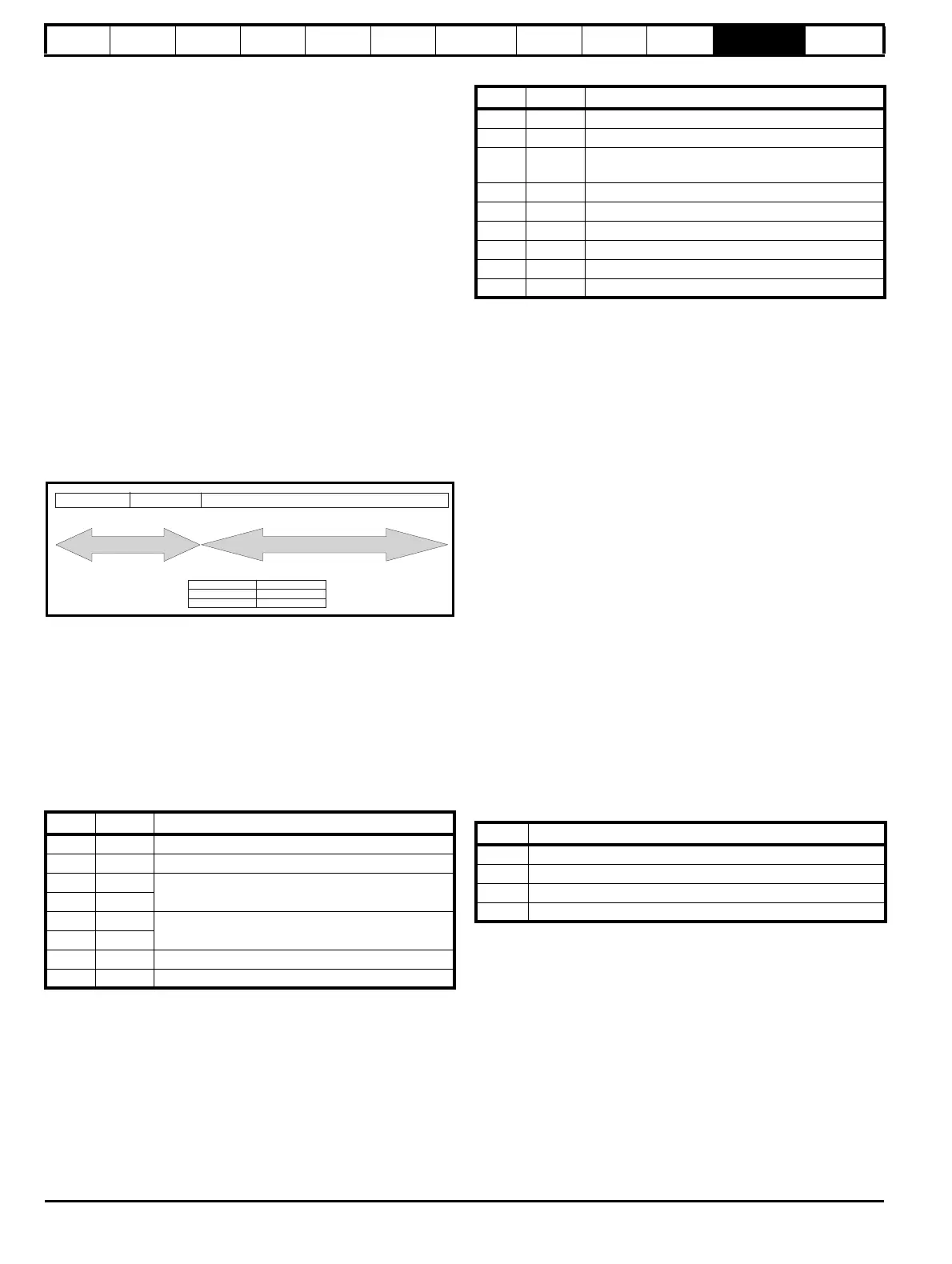
Byte Value Description
0 0x01 Slave destination node address
1 0x03 Function code 0x03
20x40
Start register Pr 00.001
(16384 + (100 x 0) + 1 – 1) = 16384 = 0x4000
30x00
40x00
Number of 16 bit registers to read
Pr 00.001 is 1 x 32 bit register = 2 x 16 bit registers
50x02
6 0xD1 CRC LSB
7 0xCB CRC MSB
bit 15
bit 14
bits 13 to 0
Register address
bit 14
Data type
0
1
16-bit
32-bit
Byte Value Description
0 0x01 Slave destination node address
1 0x03 Function code 0x03
20x04
Length of data (bytes) = 1 x 32 bit register =
4 bytes
3Pr 00.001 data
4
5
6
7 CRC LSB
8 CRC MSB
Code Description
03 Read multiple 16 bit registers
06 Write single register
16 Write multiple 16 bit registers
23 Read and write multiple 16 bit registers

 Loading...
