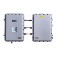
SS500e/SS2000e/SS3000e Gas Analyzers
B–14 4900002230 rev. D 2-6-20
24. Reconnect the thermistor connector.
25. Reconnect the optical cable harness.
26. Connect the new pressure sensor cable.
27. Close the door.
28. Conduct a leak test to determine that the new pressure sensor is not
leaking.
29. Turn the system power on. Refer to the Firmware Operator’s Manual
for this analyzer for “Powering up the analyzer.”
30. Run a validation on the analyzer. Refer to the Firmware Operator’s
Manual for instructions to “Start Validation.”
a. If the system passes, the pressure sensor replacement is
successful.
b. If the system does not pass, refer to“Service Contact” on
page B-23
for instruction.
Confirmingthereliefvalvesetting
Confirm that the relief valve at the field pressure reducing station has been set
to the specified setpoint. Refer to the analyzer drawings for the required
settings.
1. Remove the relief valve from the pressure reducing regulator and
connect to an adjustable pressure source.
2. Re-install the relief valve.
3. Check all connections for gas leaks. SpectraSensors recommends
using a liquid leak detector.
Do not allow cell to exceed 10 PSIG or damage could occur.
For any questions related to leak testing the pressure sensor,
refer to “Service Contact” on page B-23.
Refer to the manufacturer’s instructions for details related to
setting the relief valve.

 Loading...


