Installation
Hardware Installation and Maintenance Manual 3
–15
Configuring the optional RS-232C/Ethernet
Converter
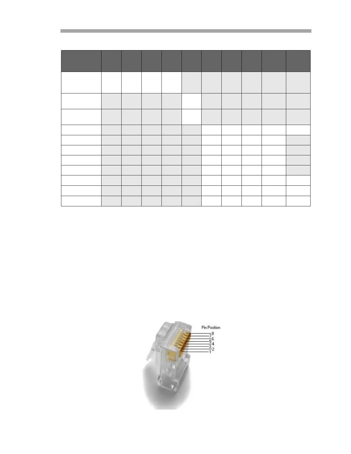
The optional RS-232C to Ethernet Converter provides a standard RJ-45
connection. Refer to Figure 3–6 for an illustration of a RJ-45 connector and pin
identification. Cable pin-outs for standard and crossover cables are listed in
Table 3–5 and Table 3–6, respectively. For additional information about the
configuration and use of the RS-232C to Ethernet converter, refer to “Ethernet
Serial Server” on page 5-1.
Table 3–4 Output signal connections (two-wire RS-485 configuration)
SW1 SW2 SW3 SW4 SW5 SW6 SW7 SW8
Time-
out
1
(ms)
R11
(KΩ)
RS-485
2-Wire
Half Duplex
ON ON ON ON
120 Ω Built-in
Termination
ON
External or no
Termination
OFF
1200 Baud
OFF OFF OFF
8.330
2
820
2400 Baud
OFF OFF ON 4.160
4800 Baud OFF ON OFF 2.080
9600 Baud ON OFF OFF 1.040
19.2K Baud ON ON ON 0.580
38.4K Baud
OFF OFF OFF
0.260
2
27
57.6K Baud
OFF OFF OFF
0.176
2
16
115.2K Baud
OFF OFF OFF
0.087
2
8.2
1. Time-out selections are equal to one character time at the indicated baud rate.
2. To achieve this time-out, an appropriate through-hole resistor must be placed in the
R11 location on the PCB.
Figure 3–6 RJ-45 Connector

 Loading...


