SS500e/SS2000e/SS3000e Gas Analyzer
3–14 4900002230 rev. D 2-6-20
10. Close and tighten the electronics enclosure cover.
11. To complete the connections, connect the other end of the current
loop wires to a current loop receiver and each serial/Ethernet cable
to a serial/Ethernet port on your computer.
Configuring the optional RS-232C/RS-485
Converter
The optional Optically Isolated RS-232C to RS-485 converter is configured for
two-wire RS-485. DIP switches on the side of the converter can be used to set
time-out and termination, as indicated in Table 3–4.
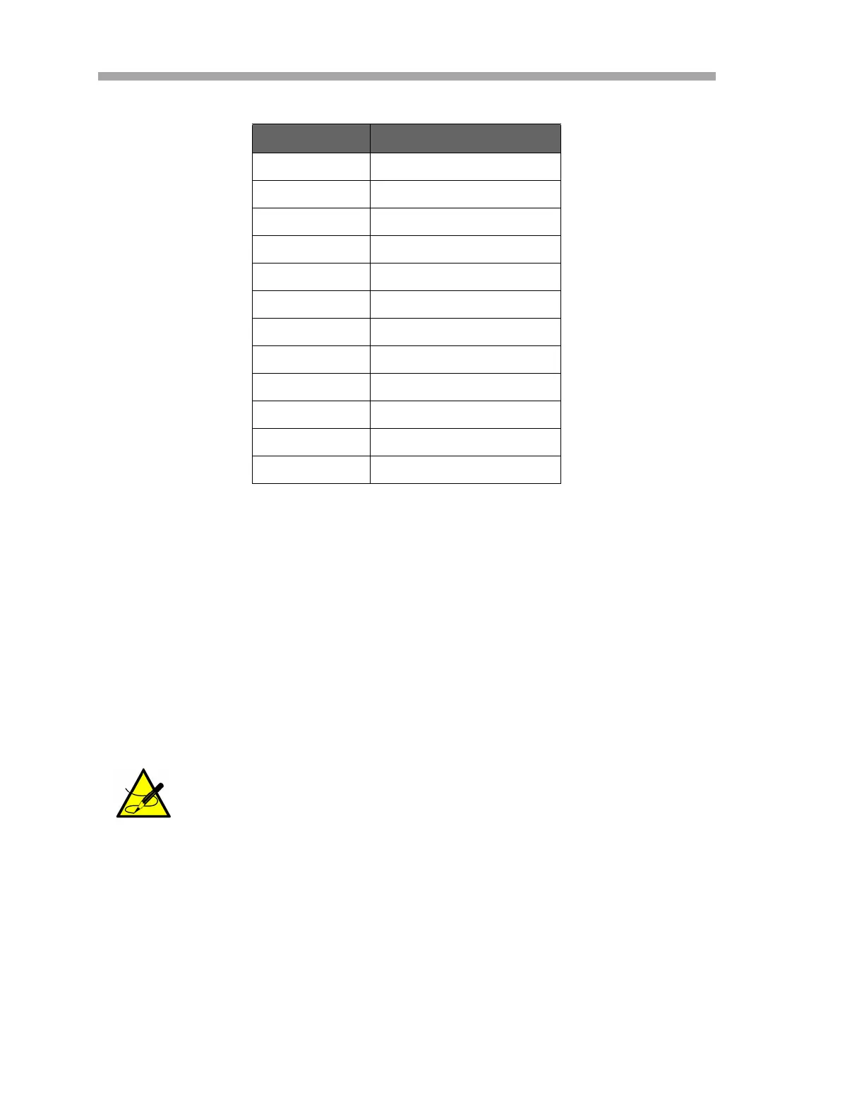
Table 3–3 Output signal connections (Ethernet configuration)
Terminal Description
1NC
2NC
3NC
4NC
5NC
6NC
7 4-20 mA Ch. A (+)
8 4-20 mA Ch. A (–)
9 4-20 mA Ch. A GND
10 4-20 mA Ch. B (+)
11 4-20 mA Ch. B (–)
12 4-20 mA Ch. B GND
RS-232C must be set to 9600 (default), whereas the RS-485
should be set to match the network settings.

 Loading...


