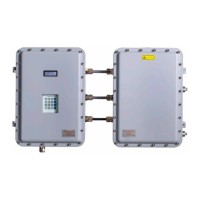
SS500e/SS2000e/SS3000e Gas Analyzer
4–8 4900002230 rev. D 2-6-20
2. Open the sample supply shut-off valve.
3. Open the bypass flowmeter control valve to establish sample flow
from the sample probe and set the flowmeter control valve to the
specified value. Refer to the system drawings in Appendix A.
4. Confirm that the sample supply pressure is set to the approximate
pressure specified under flowing conditions. Refer to the system
drawings in Appendix A.
Tostartuptheanalyzeronprocesssample
1. Ensure the low pressure flare or atmospheric vent header shut-off
valve is opened for the sample flow effluent from the SCS.
2. Open the sample flowmeter control valve(s) to approximately the
specified flow for each measurement cell. Refer to the system
drawings in Appendix A.
3. If required, adjust each sample pressure regulator to the specified
setpoint for each measurement cell.
4. Adjust the sample flowmeter control valve(s) to the specified flows
for the measurement cells.
Do not open the cell flowmeter at this point.
Make sure that no liquid, solids, etc. are flowing through the
bypass by viewing the flowmeter. If substances are present, shut
down the system and purge the lines.
Although the exact supply pressure setpoint is not critical, the
pressure at the sample system should be within 5 PSIG of the
specified supply pressure setpoint. There may be a difference
between the pressure readings at the sample tap and inside the
SCS due to the pressure drop in the sample transport line under
flowing conditions. If the pressure at the SCS under flowing
conditions is not sufficiently close to the specified setpoint, it will
be necessary to readjust the pressure regulator setpoint at the
field pressure reducing station to provide the required supply
pressure with the specified sample bypass flow.
This procedure can be completed during the system warm-up
process. Refer to the system drawings in Appendix A for all
recommended settings.

 Loading...


