SS500e/SS2000e/SS3000e Gas Analyzer
3–12 4900002230 rev. D 2-6-20
2. Run conduit from the signal/alarm receiving station to the conduit
hub on the electronics enclosure labeled for signal connections.
3. Pull the customer-supplied cable(s) for the current loop(s), alarm(s)
and serial/Ethernet connections through the conduit into the
electronics enclosure.
4. In keeping with best practices, run the wires through the provided
ferrite.
5. Wrap the wires tightly around the ferrite making sure the ferrite ends
up as close to the entry point of the wires as possible, as shown in
Figure 3–2.
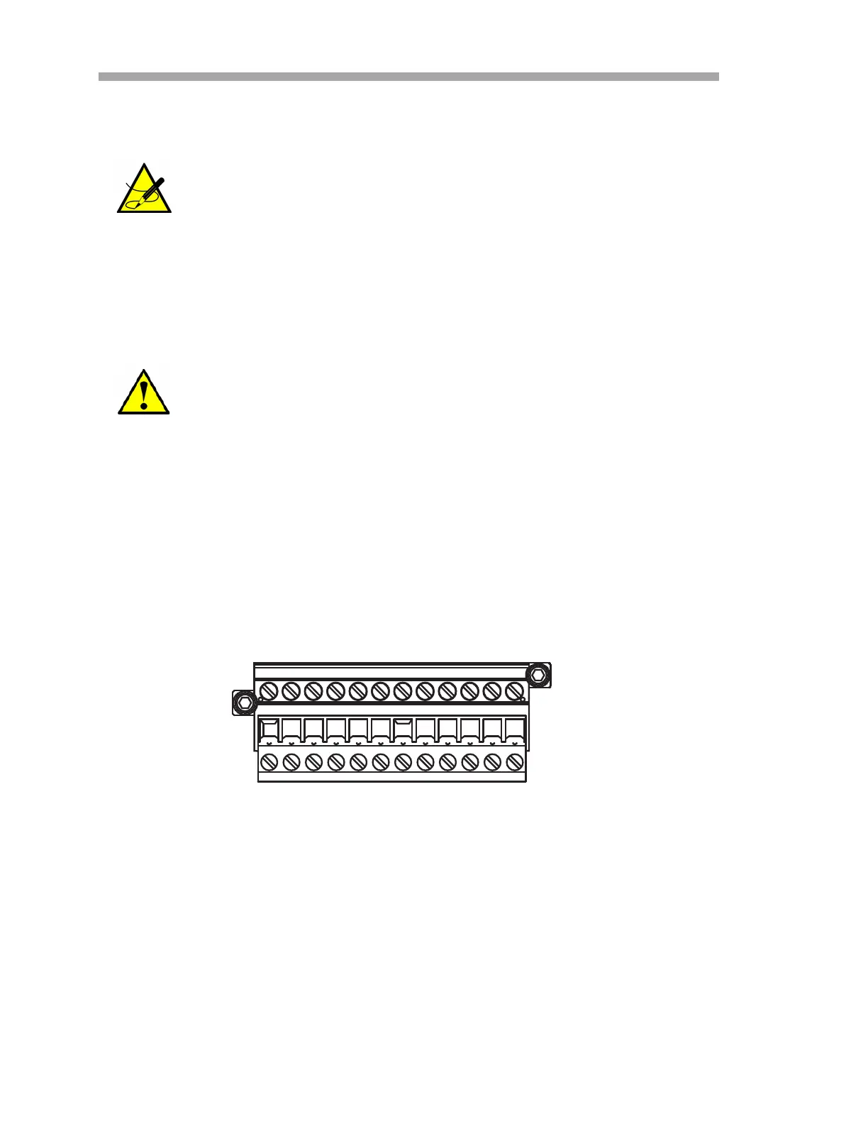
6. Strip back the jacket and insulation of the current loop and serial
cables just enough to connect to the mating terminal block (TB2),
shown in Figure 3–5. The mating terminal block can be pulled up and
removed from its base to make the cable connection process easier.
7. Connect the 4-20 mA current loop and serial signal wires to the
appropriate terminals, as indicated in Table 3–1, Table 3–2 or
Tabl e 3– 3 .
8. For systems with an optional RS-232C to Ethernet converter, plug
the male RJ-45 connector directly into the converter.
9. Reinsert the mating terminal block (TB2) into its base and verify that
each connection is secure.
Conduit seals should be used where appropriate in compliance
with local regulations.
Proper installation and use of the provided ferrite is required for
electromagnetic immunity rating.
Figure 3–5 Mating terminal block (TB2) in
electronics enclosure for connecting signal cables

 Loading...


