Introduction
Hardware Installation and Maintenance Manual 1
–9
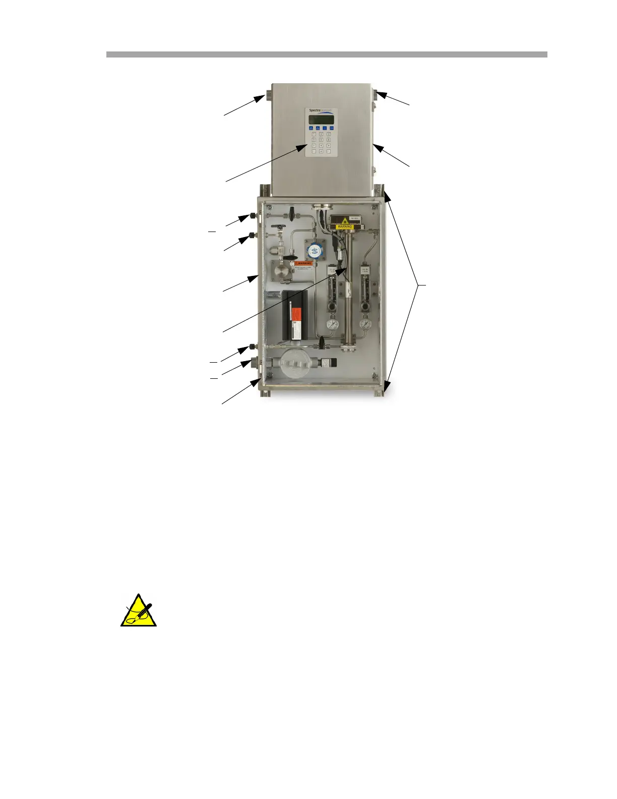
Power is connected to the analyzer from an external power source through the
top of the enclosure. The measurement cell along with flow devices to control
flow and pressure for the measurement cell and the bypass loop are mounted
inside the SCS enclosure. Refer to Chapter 4 for more information on the SCS.
Inside the SS500e/SS2000e/SS3000e analyzer electronics enclosure is the
electronics assembly. Refer to Figure 1–6 through Figure 1–11 for views of the
AC electronics assemblies and DC electronics assemblies.
The circled area in Figure 1–6 highlights the optional RS-232C to
RS-485 converter. For analyzers configured with an RS-232C
connection only, the converter is not installed on the electronic
assembly, which will use different cables for connections.
Figure 1–5 SS500e/SS2000e architecture overview
KEYPAD/ WINDOW
PLATE/LCD
4X MOUNTING FEET
7/16 in. SLOTTED
HOLE
SAMPLE RETURN
POWER INPUT
SAMPLE PORT/VAL
GAS SUPPLY
SIGNAL
WIRING
SAMPLE
MEASUREMENT CELL
ANALYZER
ELECTRONICS
ENCLOSURE
SAMPLE
CONDITIONING
SYSTEM (SCS)
SAMPLE SUPPLY
CHASSIS
GROUND
HEATER POWER

 Loading...


