Section 15: Servicing the Legend
181
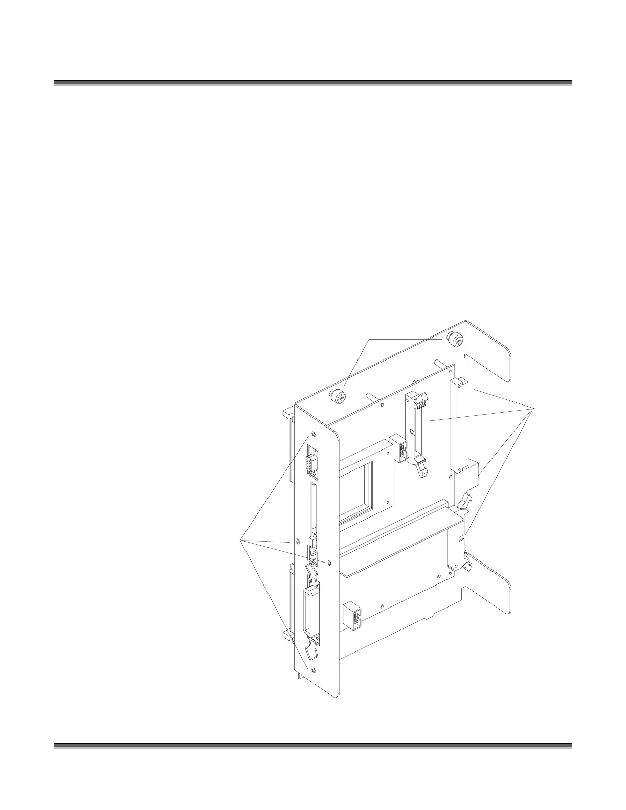
Connectors
(four)
Captive Screws
(two)
Phillips Screws
(four)
Controller
The controller (part #LM1) is located on the Legend EX machines in the controller
bay, and is the main electronic component module for the Legend; see the “SERVICE
MODULE LOCATION DIAGRAM LEGEND 24 and 32 EX” shown in a diagram.
On the Legend TT, this is in the back of the machine, and is the main electronic
component module for the Legend; see the “SERVICE MODULE LOCATION
DIAGRAM #2 LEGEND TT” shown on previous page. To remove and/or service
this module, first turn the machine off and unplug the power cord from the machine
or from the wall. Demate the four connectors shown in the diagram below. Then
remove the screws shown in the diagram. The captive screws are inside the machine,
and the four Phillips screws are on the outside. The assembly can now be lifted up
and out of the machine.
Then install the
replacement. Please be
careful to make sure all
the connectors are fully
seated. Please do not
forget to return the
failed component to
Epilog.
 Loading...