Epson Artisan 700/Epson Stylus Photo PX700W/TX700W Revision C
DISASSEMBLY/ASSEMBLY Disassembly Procedures 131
Confidential
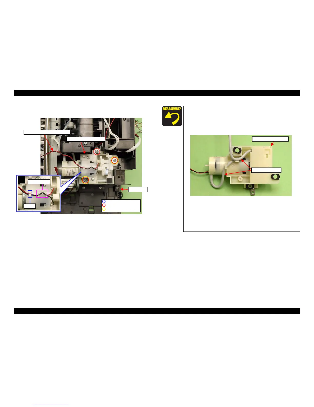
3. Remove the screws (x3) that secure the Decompression Pump Unit, and
remove the Decompression Pump Unit from the Base Frame.
Figure 4-72. Removing the Decompression Pump
Unit
Base Frame
Decompression Pump Unit
Hook
Dowels (x6)
Decompression Pump Motor cable
P.W. 3.3x0.5x10
C.B.P. 3x14 (6±1Kgfcm)
C.B.P. 3x8 (6±1Kgfcm)
When routing the Decompression Pump Motor cable, make
sure to secure it with the dowels (x6) and the hook on top of the
Decompression Pump Unit as shown in Fig. 4-72.
When routing the decompression tube, confirm no clippe
d part
or fold on the tube. (See Fig. 4-71, Fig. 4-73.)
Figure 4-73. Installing the Decompression Pump Unit
Put the decompression tube through the groo
ve on the Base
Frame (section A, B), and route it behind the
FFC. (See Fig.
4-71.)
Make sure to insert the decompression tube into the socket on
the Cartridge Box Unit to the fu
ll to its base. (See Fig. 4-71.)
Decompression Pump Unit
Decompression tube