Epson Artisan 700/Epson Stylus Photo PX700W/TX700W Revision C
ADJUSTMENT Adjustment Using Adjustment Program 225
Confidential
5.2.7 PG Offset Value Adjustment
Overview
To compensate the deviation of the PG position (see Table5.3.1 (p235)) d
erived from
the difference of the result of PG Adjustment (p235) due to individual variability of the
mechanism, write the notch positions of the parallelism adju
stment bushings when PG
Adjustment (p235) is performed into EEPROM to correct the PG position during APG
operation.
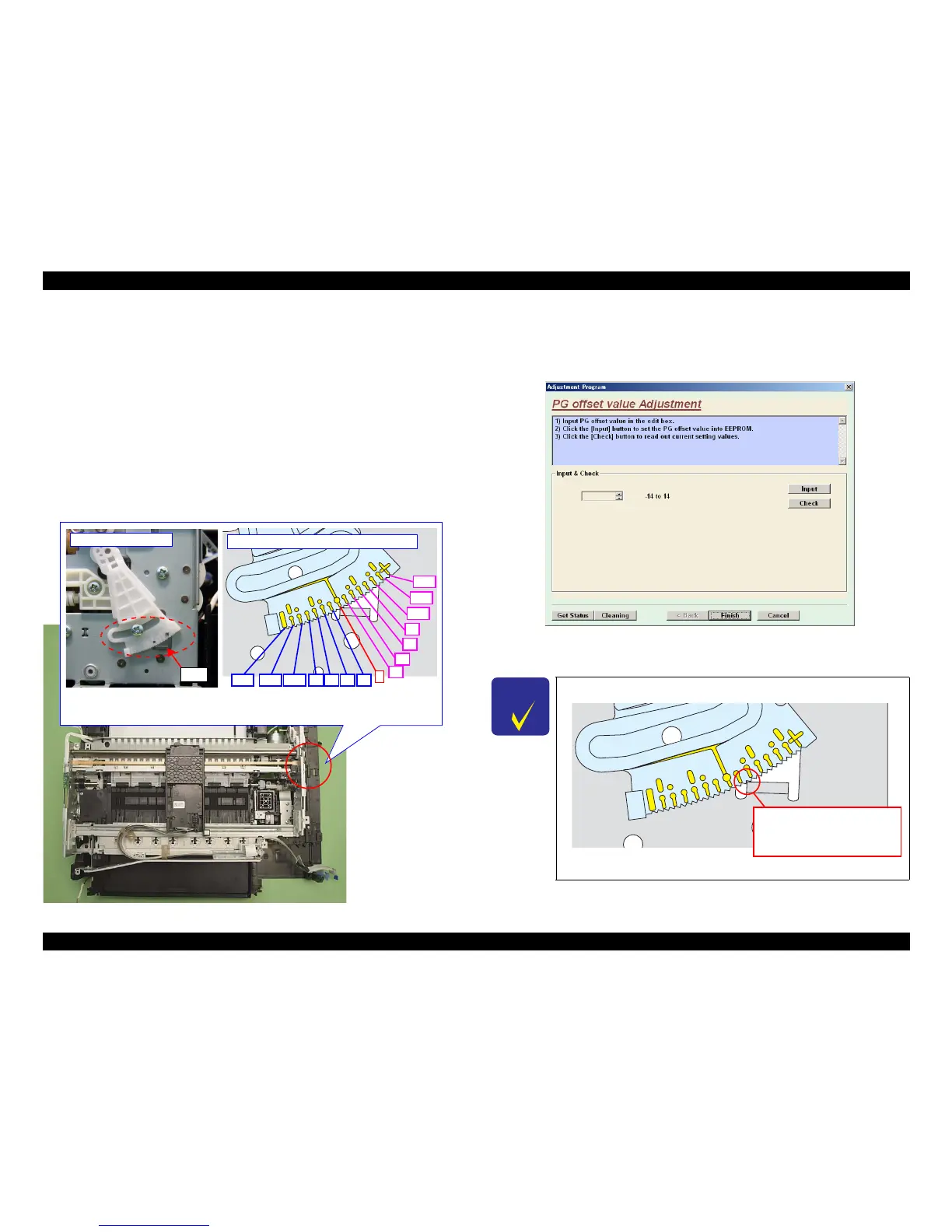
Preparation
After PG Adjustment (p235) is com
plete, check the notch position of the parallelism
adjustment bushing at the rear on the 0-column side and note down the offset value
according to the figure below.
Figure 5-11. Ch
ecking the PG Offset
Setting procedure
1. Start the adjustment program, and select “PG offset value Adjustme
nt” from the
menu.
Figure 5-12. PG offset value Adjustment Screen
2. Enter the PG offset value noted down in advance, and press “Input” button.
Rear on 0-column side
Rib
+4
0
-8 -4-12 -10 -6 -2
Conversion of notch position to offset value
-14
+14
+12
+10
+8
+2
+6
Bushing at the rear on 0-column side has scales in every 2 offsets (notches). As offset
value 0 in center and 1 notch for 1 offset, note down the notch position of bushing
engaged on the rib on the frame.
C H E C K
P O I N T
The following is a sample of the PG offset value.
Figure 5-13. Sample of the PG offset value
Enter “+3” into adjustment
program because the notch
position of bushing engaged on
the rib is +3 from the center.