Epson Artisan 700/Epson Stylus Photo PX700W/TX700W Revision C
DISASSEMBLY/ASSEMBLY Disassembly/reassembly procedures specific to Artisan 700/PX700W/TX700W 200
Confidential
2. Disconnect the AID cable from the connector on the SUB Board, and remove
the Card Slot Assy.
Figure 4-239. Removing the Card Slot Assy (2)
4.3.3 Disassembling the Scanner Unit (Artisan 700/
PX700W/TX700W)
4.3.3.1 Document Cover
Parts/Components need to be removed in advance:
Scanner Unit/ADF Unit
Removal procedure
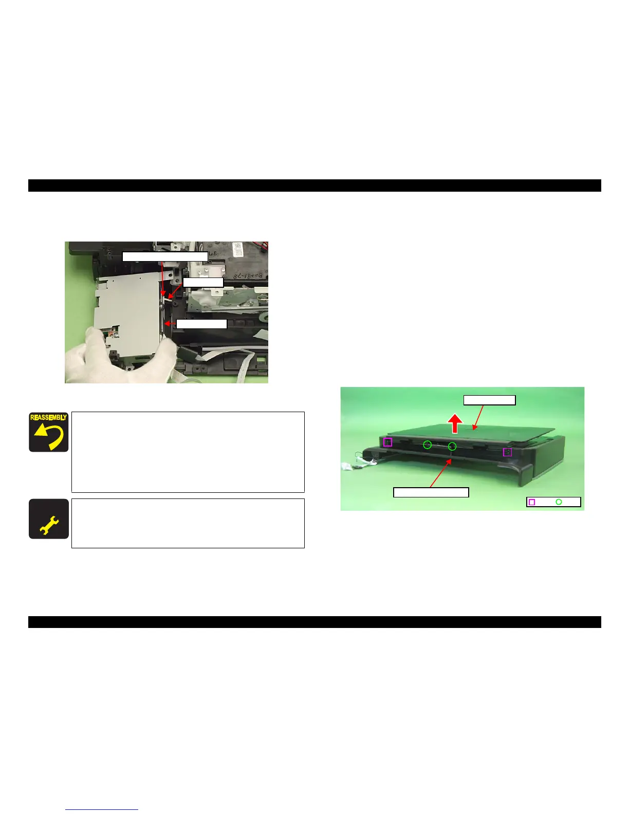
1. Release the dowels (x2) and ribs (x2) of th
e Document Cover with the
Document Cover closed, and remove the Document Cover from the Scanner
Upper Housing in the direction of the
arrow.
Figure 4-240. Removing the Document Cover
Connect the AID cable properly to the connector on the SUB
Board. (See Fig. 4-239.)
Align the grooves (x2) of the Card Slot Assy with the dowels (x
2)
of the Base Frame. (See Fig. 4-238.)
When attaching the Grounding Plate, install it over the Card
Slot Assy, and tighten them together with the screw. (See Fi
g.
4-238.)
For routing the FFCs, see 4.4 "Routing FFC/cables" (p202).
A D J U S T M E N T
R E Q U I R E D
After removing/replacing the Card Slot Assy, make the specified
adjustments. (See
Chapter 5 "ADJUSTMENT".)
AID cable
Card Slot Assy
Connector on the SUB Board
C H E C K
P O I N T
Dowel
Rib
Scanner Upper Housing
Document Cover