Epson Artisan 700/Epson Stylus Photo PX700W/TX700W Revision C
DISASSEMBLY/ASSEMBLY 194
Confidential
4.3.2 Removing the Circuit Board (Artisan 700/PX700W/
TX700W
)
4.3.2.1 Panel Unit (Artisan 700/PX700W/TX700W)
Parts/Components need to be removed in advance:
Scanner Unit/Upper Left Housing/Paper Guide Top Assy/Upper Housing
Removal procedure
1. Open the Panel Unit. (See Fig. 4-226.)
2. Lift the Right Hinge and detach the Panel FFC Guide from
the Upper
Housing.
Figure 4-226. Removing the Panel Unit (1)
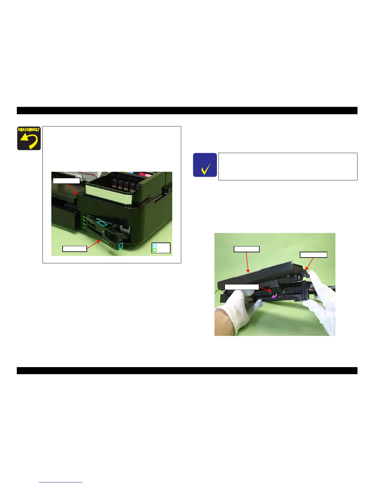
Align and insert the positioning hole of the Right Housing to the
dowel of the Base Frame. (See Fig. 4-222)
Attach the Card Cover after installing the Right Ho
using to the
printer.
When attaching the Card Cover, insert the ribs (x2) of the Card
Cover to the insi
de of the Right Housing, and secure it with the
hooks (x2).
Figure 4-225. Attaching the Card Cover
Hook
Rib
Right Housing
Card Cover
C H E C K
P O I N T
The disassembly/reassembly procedures for Artisan 800/PX800FW/
TX800FW differ from those of Artisan 700/PX700W/TX700W, see
4.2.3.1 "Panel Unit" (p115) for the procedures.
Panel Unit
Right Hinge
Panel FFC Guide