Epson Artisan 700/Epson Stylus Photo PX700W/TX700W Revision C
DISASSEMBLY/ASSEMBLY Disassembly Procedures 169
Confidential
4.2.5.3 Scanner Carriage Unit
Parts/Components need to be removed in advance:
Scanner Unit/ADF Unit/ Scanner Upper Housi
ng/Scanner Motor Unit
Removal procedure
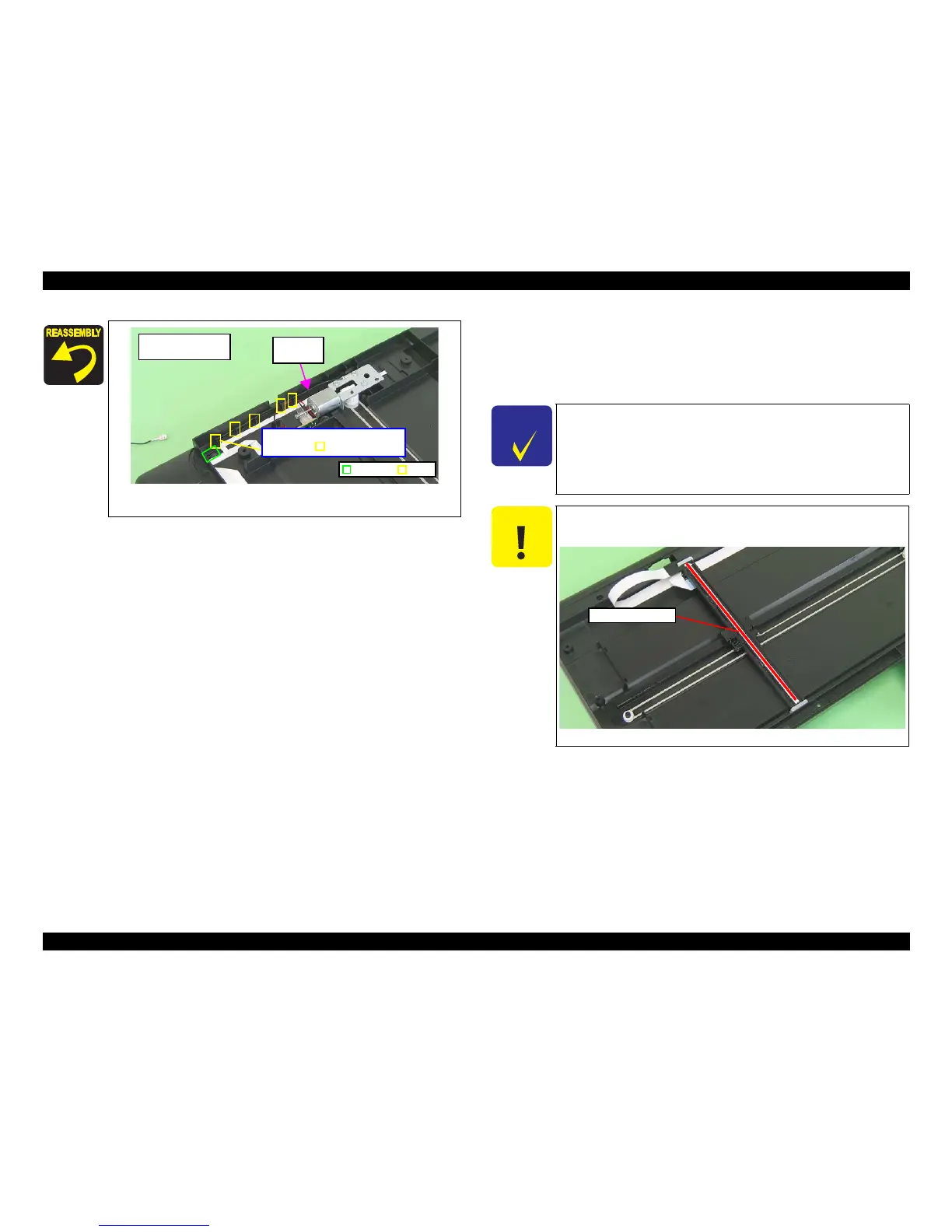
Figure 4-166. Routing the Grounding Wire
(Artisan 700/PX700W/TX700W)
Artisan 700/
PX700W/TX700W
Rib
Route the Grounding Wire between
the ribs (x5) and frame.
Groove
Grounding
Wire
C H E C K
P O I N T
Some of the parts of Artisan 800/PX800FW/TX800FW differ from
those of Artisan 700/PX700W/TX700W.
Unless otherwise specified, this section describes the procedures for
Artisan 800/PX800FW/TX800FW.
The differences that may affect
the disassembly/reassembly procedures of Artisan 700/PX700W/
TX700W will be provided in “Reassembly”, etc.
C A U T I O N
Be careful no to damage the Rod Lens Array when removing
Scanner Carriage Unit.
Figure 4-167. Handling the Scanner Carriage Unit
Rod Lens Array