Epson Artisan 700/Epson Stylus Photo PX700W/TX700W Revision C
DISASSEMBLY/ASSEMBLY Disassembly Procedures 134
Confidential
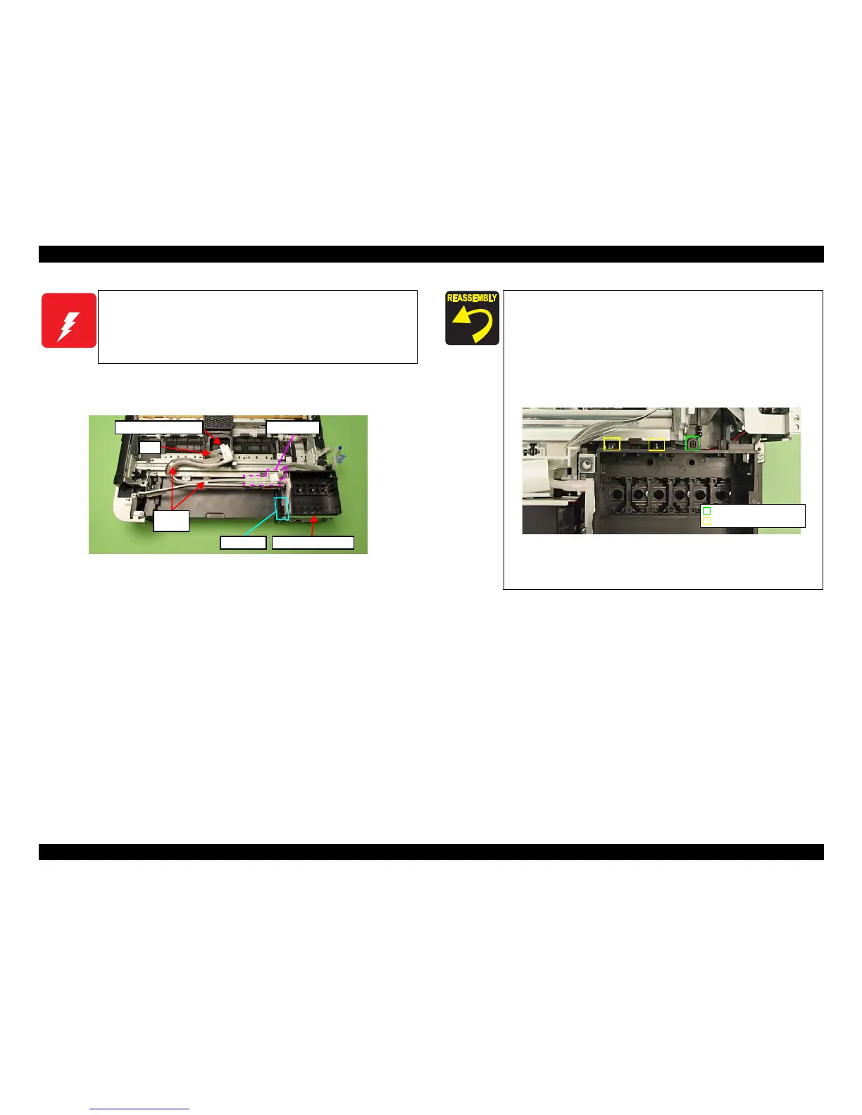
5. Release the Clamp Tubes (x2). (See Fig. 4-79.)
6. Release the Ink Supply Tube Assy and FFC from the FFC Holder, and remove
the In
k Supply IC Holder Assy.
Figure 4-79. Removing the Ink Supply Tube Assy
W A R N I N G
To prevent ink leakage, make sure not to separate the Ink Supply
Tube Assy and the Cartridge Box Unit by removing the screws (x2)
on the section A shown in
Fig. 4-79. Loosening the screws on the
section A even just once will cause ink leakage, therefore, make sure
to replace the Ink Supply IC Holder Assy with
a new one.
Cartridge Box Unit
Ink Supply Tube Assy
FFC
Clamp
Tube
FFC Holder
Section A
Make sure to insert the decompression tube into the socket on
the Cartridge Box Unit to the full to its base. (See Fig. 4-71.)
Make sure to align the positioning hole (x1) on the Cartridge
Box Unit with the dowel
(x1) of the Base Frame when
reassembling them. (See Fig. 4-80.)
When installing the Cartridge Box Unit, make sure to secure
the hooks
(x2) on the Main Frame to their positioning holes
(x2). (See Fig. 4-80.)
Figure 4-80. Installing
the Cartridge Box Unit
Ma
ke sure to attach the grounding plate to the place shown in
Fig. 4-78, and secure it with the
screw.
Positioning hole & dowel
Positioning hole & hook