Epson Artisan 700/Epson Stylus Photo PX700W/TX700W Revision C
DISASSEMBLY/ASSEMBLY Disassembly Procedures 162
Confidential
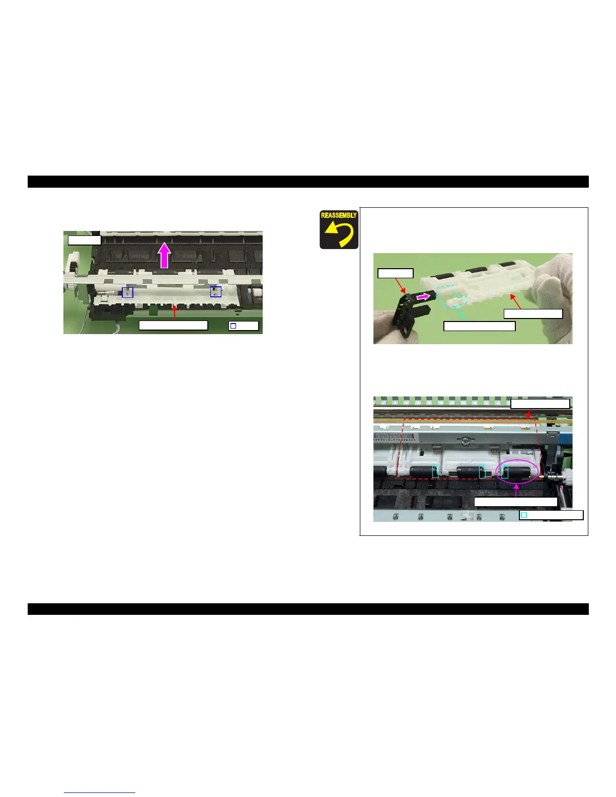
4. Release the hooks (x2) of the Main Frame and remove the Upper Paper Guide
R in the direction of the arrow.
Figure 4-150. Removing the Upper Paper Guide R
Hook
Rear side
Upper Paper Guide R
Align the positioning hole of the PE Sensor with the dowel of
the Paper Guide Front Assy. (See Fig. 4-149.)
When installing the PE Sensor, insert the sensor with the Upper
Paper Guide sheet in between. (See Fig. 4
-149, Fig. 4-151.)
Figure 4-151. Installing the PE Sensor
The roller of the Upper Paper Guide
R in the figure below only
is installed in the opposite
direction; therefore, make sure to
install it properly when the roller comes off.
Figure 4-152. Installing the
roller
PE Sensor
Upper Paper Guide sheet
Upper Paper Guide R
Roller’s convex part
Upper Paper Guide R
Roller to be installed reversely