Epson Artisan 700/Epson Stylus Photo PX700W/TX700W Revision C
DISASSEMBLY/ASSEMBLY Disassembly Procedures 104
Confidential
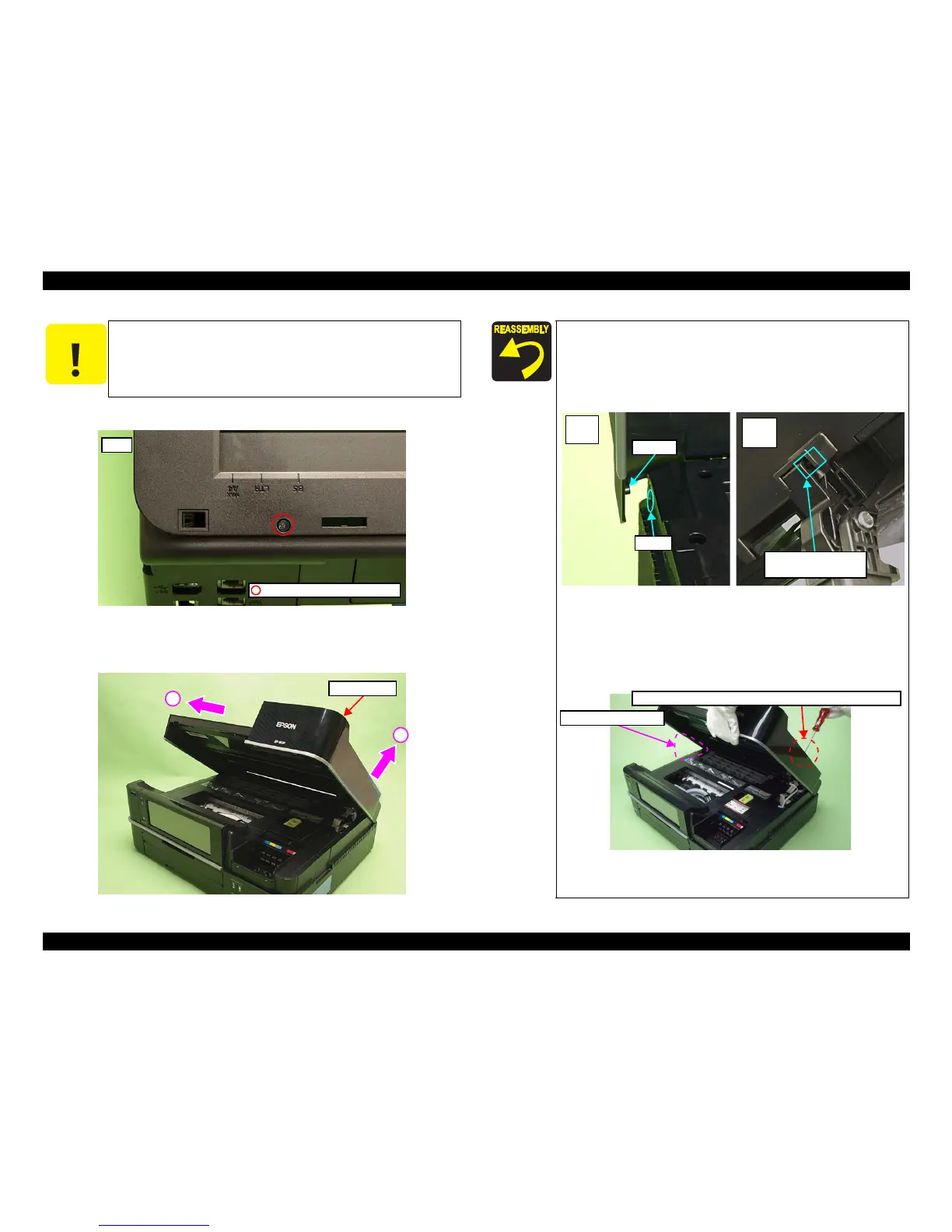
4. Remove the screw (x1) that secures the Scanner Unit.
Figure 4-7. Removing the Scanner Unit (2)
5. Lift
the Hinge on the right side in the direction of the arrow (1) and slide
the
Scanner Unit in the direction of the arrow (2), and remove it.
Figure 4-8. Removing the Scanner Unit (3)
C A U T I O N
Do not open/close the Scanner Unit with the screws removed to
avoid damage of the Scanner Unit Hinge.
Rear
C.B.P. 3x10 (black) (6±1Kgfcm)
Scanner Unit
1
2
When installing the Scanner Unit, follow the procedure below.
1. Align and insert the dowel of the Scanner Unit to the
positioning hole of the prin
ter (Left inside).
2. Align and insert the rib of the Scanner Unit to the groove o
f
the Hinge.
Figure 4-9. Installing the Scanner Unit (1)
3. While aligning the screw holes with the Scanner Unit open,
secure them temporarily with the screw
(x1) shown in Fig.
4-7. (It is recommended to prepare a pillow-shaped
supporter to keep this position.)
Figure 4-10. Installing
the Scanner Unit (2)
(Continued to the next pag
e.)
Hole
Dowel
Left
inside
Rib of the Scanner Unit
& groove of the Hinge
Right
inside
Pillow-shaped supporter
Secure it with the screw temporarily with the screw holes aligned.