Epson Artisan 700/Epson Stylus Photo PX700W/TX700W Revision C
DISASSEMBLY/ASSEMBLY Disassembly Procedures 108
Confidential
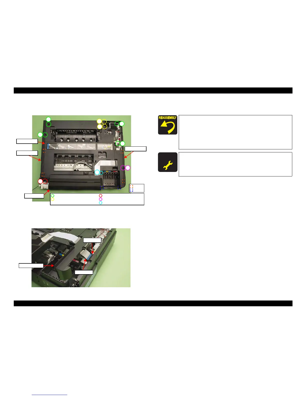
3. Remove the screws (x9) that secure the Upper Housing. (See Fig. 4-17.)
4. Release the ribs (x4) and hook
s (x2) of the Upper Housing.
Figure 4-17. Removing the Upper Housing (2)
5. Lift the Upper Housing slightly and disconnect the Panel FFC from the Main
Board, and remo
ve the Upper Housing together with the Panel Unit.
Figure 4-18. Removing the Upper Housing (3)
6. Remove the Panel Unit from the Upper Housing. (See 4.2.3.1 "Panel Unit"
(p115).)
1
2
3
4
5
7
8
6
Panel Unit
9
C.B.S. 3x6 (8±1Kgfcm)
C.B.S. 3x8 (black) (8±1Kgfcm)
C.B.P. 3x10 (6±1Kgfcm)
C.B.A. 3x8 (black) (6±1Kgfcm)
C.B.P. 3x10 (black) (6±1Kgfcm)
Rib
Hook
Upper Housing
Left Housing
Right Housing
Panel FFC
Main Board
Upper Housing
Insert the ribs (x4) of the Upper Housing to the inside of the
Housing L/R when installing the Upper Housing. (See Fig.
4-17.)
Tighten the screws in the order shown in Fig. 4-17.
When installing the Front Harness Cover, insert the ribs (x3) of
the Front Harness Cover to the Upper Hous
ing, and secure
them with the hooks (x2). (See Fig. 4-16.)
A D J U S T M E N T
R E Q U I R E D
After removing/replacing the Upper Housing, make the specified
adjustments. (See
Chapter 5 "ADJUSTMENT".)