Epson Artisan 700/Epson Stylus Photo PX700W/TX700W Revision C
DISASSEMBLY/ASSEMBLY Disassembly Procedures 116
Confidential
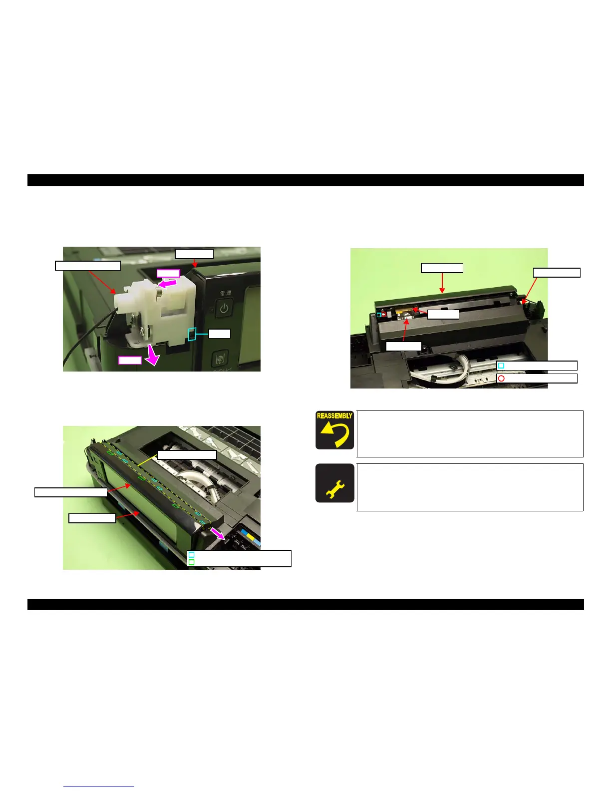
4. Slide the Ratchet Holder Assy to the left, and release the rib A. (See Fig.
4-36.)
5. Slide the Ratchet Holder Assy to the front to remove it from the Upper
Housing, and rem
ove it from the Panel Unit.
Figure 4-36. Removing the Ratchet Holder Assy (2)
6. Release the hooks (x3) of the Fron
t Panel Unit Cover. (See Fig. 4-37.)
7. Slide the Upper Panel Cover in the direction of the arrow to release the hooks
(x6), and remove th
e Upper Panel Cover.
Figure 4-37. Removing the Panel Unit (1)
8. Dis
connect the Panel FFC from the connector of the Panel Unit. (See Fig.
4-38
.)
9. Remove the screw (x1) that secures the Panel Unit and remove the Panel Unit
from the Upper Hou
sing.
Figure 4-38. Removing the Panel Un
it (2)
Step 4
Rib A
Panel Unit
Step 5
Ratchet Holder Assy
Front Panel Unit Cover
Panel Unit
Upper Panel Cover
Hook of the Upper Panel Cover
Hook of the Front Panel Unit Cover
Align and insert the dowel of the Right Hinge to the positioning
hole of the Panel Unit. (See Fig. 4-38.)
Insert the rib A of the Ratchet Holder Assy to th
e position
shown in Fig. 4-36. (See Fig. 4-36.)
A D J U S T M E N T
R E Q U I R E D
After removing/replacing the Panel Unit, make the specified
adjustments. (See
Chapter 5 "ADJUSTMENT".)
Positioning hole & dowel
C.B.P. 3x10 (6±1Kgfcm)
Panel Unit
Panel FFC
Connector
Upper Housing