REV.-A
A
. . .
-.
—/e
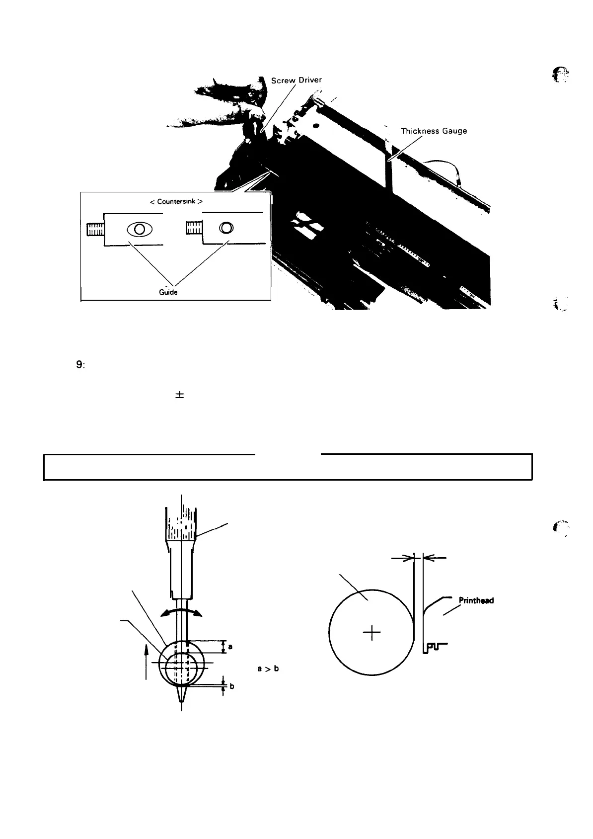
<
Countersink
>
I
Large
Small
I I
\
Carriage
Guide
Shaft B
‘~
Step
9:
Step 10:
Step 1 1:
Figure 4-54. Platen Gap Adjustment
Set the head adjustment lever at the 2nd position.
Push the paper release lever all the way back.
Gap value: 0.51
f
0.05 mm
Adjust the platen gap using a thickness gauge while rotating carriage guide shaft B in the
direction of the arrow in Figure 4-55.
WARNING
At this time, the paper release lever must be in the friction feed position. (Do not turn it forward.)
carriage
I
l!
I
!1
I
I
1,
1,
I
I
I
~
Screwdriver
Guide Shaft B
‘
screw
up
a>b
Figure 4-55. Eccentric of Carriage Guide Shaft B
4-38
c
.,
.:?!
#-..S,,
..-
. .
.
0.51 * 0.05 mm
-
-
Platen
Printhead
</
Figure 4-56. Platen Gap

 Loading...


