EasyManua.ls Logo

Epson RC90 - Motion Range Setting by Mechanical Stops

Epson RC90
124 pages
To Next Page IconTo Next Page
To Previous Page IconTo Previous Page
Loading...
1. Safety
Safety and Installation (RC90 / EPSON RC+ 7.0) Rev.6 41
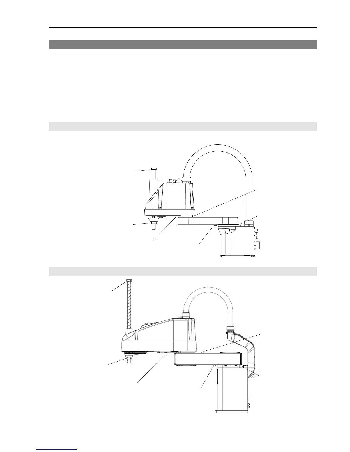
1.10 Motion Range Setting by Mechanical Stops
Mechanical stops physically limit the absolute area that the Manipulator can move.
Both Joints #1 and #2 have threaded holes in the positions corresponding to the
angle for the mechanical stop settings. Install the bolts in the holes
corresponding to the angle that you want to set.
Joints #3 can be set to any length less than the maximum stroke.
LS3 / LS6
Mechanical stop of Joint #2
(Fixed)
Mechanical stop of
Joint #1 (Adjustable)
Mechanical stop of Joint #3
(Lower limit mechanical stop)
(Do not move the upper
limit mechanical stop.)
Mechanical stop of
Joint #1 (Fixed)
Mechanical stop of
Joint #2 (Adjustable)
LS20
Mechanical stop of Joint #2
(Fixed)
Mechanical stop of
Joint #1 (Adjustable)
Mechanical stop of Joint #3
(Lower limit mechanical stop)
(Do not move the upper
limit mechanical stop.)
Mechanical stop of
Joint #1 (Fixed)
Mechanical stop of
Joint #2 (Adjustable)

Table of Contents

Other manuals for Epson RC90

Related product manuals