2. Installation
Safety and Installation (RC90 / EPSON RC+ 7.0) Rev.6
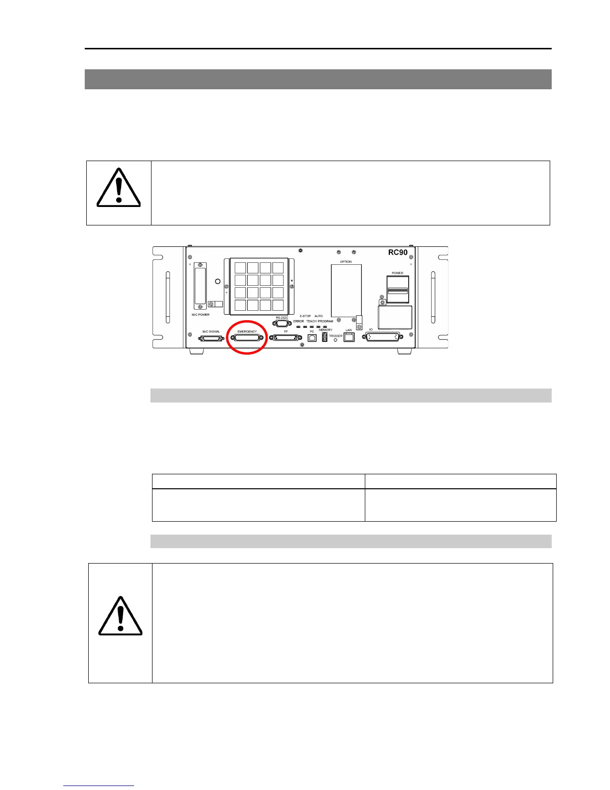
2.6 Connection to EMERGENCY Connector (Controller)
Connect a safeguard switch or Emergency Stop switch to the Controller
EMERGENCY connector for safety.
When nothing is connected to the EMERGENCY connector, Controller does not
operate normally.
WARNING
Before connecting the connector, make sure
that the pins are not bent.
the pins bent may damage the connector and result in
2.6.1 Safety Door Switch and Latch Release Switch
The EMERGENCY connector has input terminals for the Safety Door switch and
the Emergency Stop switch. Be sure to use these input terminals to keep the
system safe.
EMERGENCY connector
(Controller side)
D-sub 25 Pin (male)
Mounting style #4-40
2.6.2 Safety Door Switch
WARNING
The interlock of the Safety Door must be functioning when the
is operated. Do not operate the system under the condition that
the switch cannot be turned ON/OFF (e.g. The tape is put around the
switch.). Operating the robot system when the switch is not
is extremely hazardous and may cause serious safety problems
as the Safety Door input cannot fulfill its intended function

 Loading...


