SC-T7000 series/SC-T5000 series/SC-T3000 series Revision B
DISASSEMBLY & ASSEMBLY Disassembly and Assembly Procedure 124
Confidential
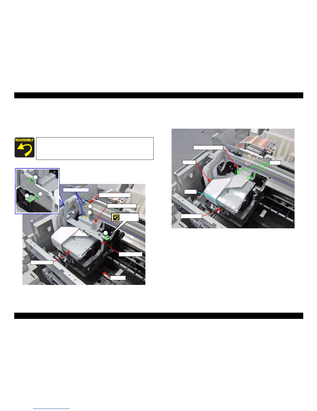
12. Move the CR UNIT on the Platen.
13. Remove the six screws, and remove the CR Sub Fixing Plate.
B) Silver M3x10 Machine screw: 4 pcs
C) Silver M3x8 S-tite screw with built-in washer: 2 pcs
Figure 3-55. Removing the CR Sub Fixing Plate
14. Disconnect the CR FFC from the connector (CN100) of the SUB BOARD.
15. Release the CR FFC from the two hooks of the Ferrite Core Holder, and place the
CR FFC over the rear of the printer temporarily.
Figure 3-56. Releasing the CR FFC
Secure the Grounding wire and the plate with the same screw
shown in the below figure.
Pay attention to the positioning points (See Figure 3-55).
B
B
B
CR Sub Fixing Plate
B
C
C
Grounding wire
CR Sub Tube Frame
DAMPER KIT
CR UNIT
Screw
together
Positioning points
CR FFC
SUB BOARD
CN100
Ferrite Core Holder
Hooks
 Loading...