SC-T7000 series/SC-T5000 series/SC-T3000 series Revision B
DISASSEMBLY & ASSEMBLY Disassembly and Assembly Procedure 132
Confidential
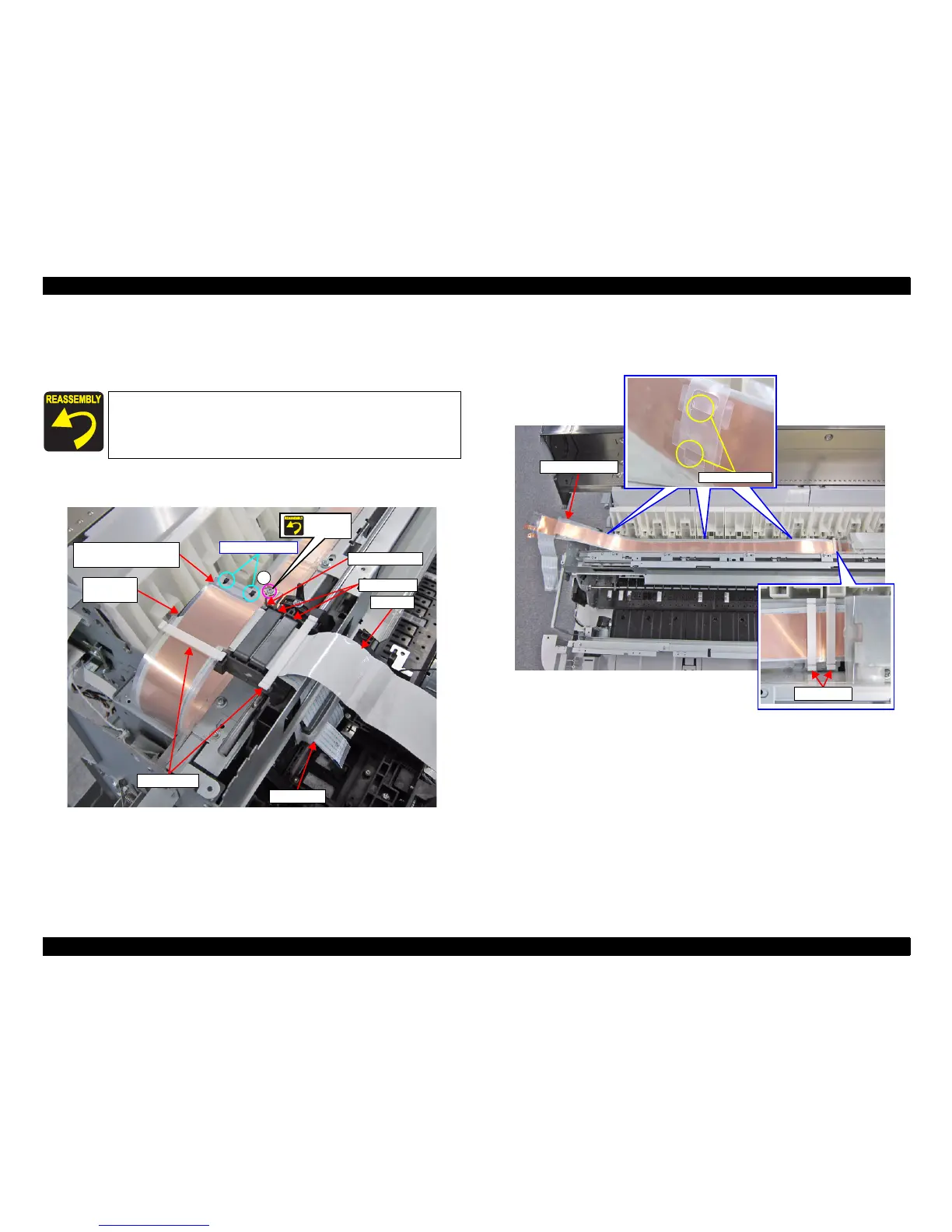
15. Remove the FFC clamps.
16. Remove the screw that secures the FFC Shield Plate.
A) Silver M3x6 S-tite screw with built-in washer: 1 pcs
17. Pull out the CR FFC and HEAD FFC from the two Ferrite Cores.
Figure 3-69. Removing the CR FFC (Top of the CR UNIT)
18. Disengage the three joints from the two each holes on the FFC Sheet Guide.
19. Remove the two FFC clamps.
Figure 3-70. Releasing the FFC (1)
Secure the Grounding wire and the plate with the same screw
shown in the below figure.
Pay attention to the positioning points (See Figure 3-69).
A
FFC Clamps
CR FFC
Ferrite Core
Carriage
Main Assy
FFC Shield Plate and
Lower FFC Sheet Guide
Grounding wire
HEAD FFC
Screw
together
Positioning points
Joints and holes
FFC Sheet Guide
FFC Clamps
 Loading...