SC-T7000 series/SC-T5000 series/SC-T3000 series Revision B
DISASSEMBLY & ASSEMBLY Disassembly and Assembly Procedure 134
Confidential
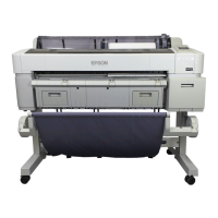
22. Remove the four FFC clamps on the side of the Rear Main Frame.
Figure 3-73. Releasing the FFC (2)
23. Peel off the CR FFC.
Figure 3-74. Releasing the FFC (3)
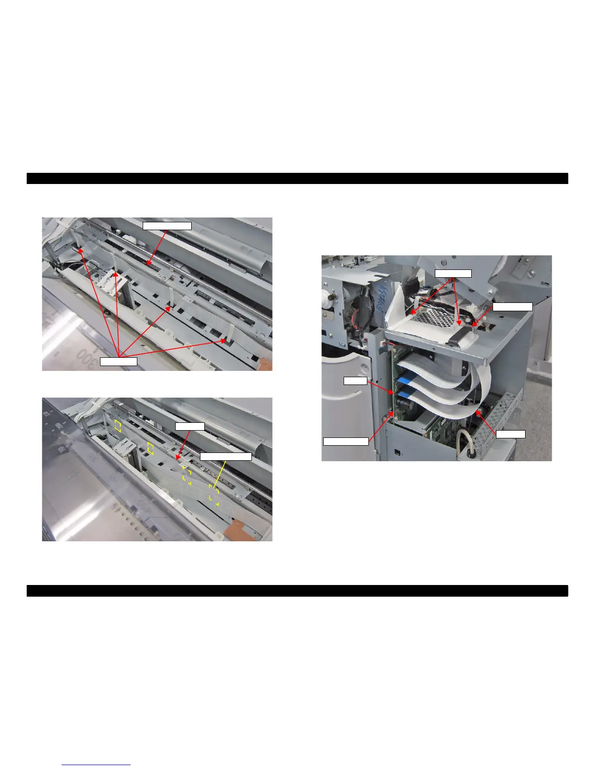
24. Remove the two FFC clamps from the top of the Board Box.
25. Disconnect the CR FFC from the connector (CN100) of the MAIN BOARD, and
pull it from the hole of the Board Box.
26. Pull out the CR FFC from the Ferrite Core on the Board Box.
Figure 3-75. Removing the CR FFC (Around the Board Box)
Rear Main Frame
FFC Clamps
CR FFC
Double-sided tape
MAIN BOARD
CR FFC
CN100
Ferrite Cores
FFC Clamps
 Loading...