4.2.5.3 Removing the CR Motor Assembly
1. Remove the housing. (Refer to Section 4.2.1)
2. Pull out the circuit board tray as described in “Removing the Circuit Board Tray” on
page96, and disconnect the CR motor cable from CN7.
3. Rotate Gear 73.6 toward you (front??) to release the carriage lock mechanism, and then
move the carriage to the center.
4. Loosen the timing belt by pushing the driven pulley holder to the inside of the side
frame, and remove the timing belt from the pulley on the CR motor.
5. Remove two screws (CBS 3x6) and remove the CR motor assembly.
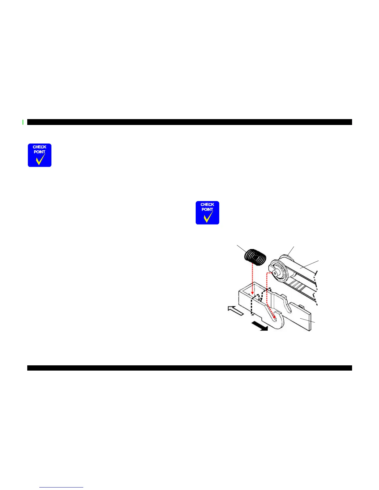
Figure 4-9. Removing the Timing Belt
When reinstalling the PF motor, keep the following in mind.
n Be careful of the direction of the cable from the PF motor
assembly.
n Tie a plastic tie band around the PF motor cable; see step 5
above.
n Be very careful of the grooves in the gears during disassembly
and assembly.
When reinstalling the timing belt, make sure the driven pulley
assembly fits tightly in the angled slots in the driven pulley holder.
(Refer to Figure 4-9.)
Compression Spring 19.6
Driven Pulley
Assembly
Timing
Belt
To the outside of
the frame
To the inside of the
frame
Driven Pulley
Holder
 Loading...