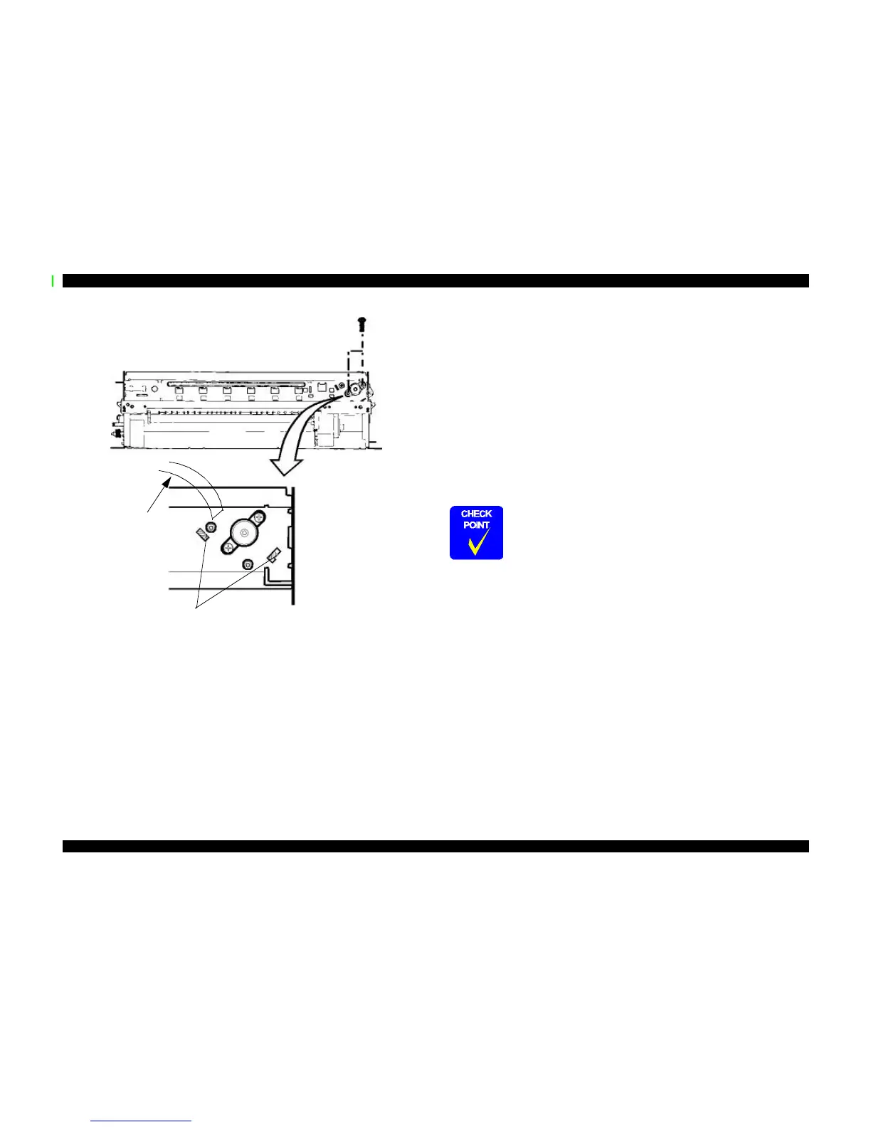
Figure 4-10. Removing and Installing the CR Motor Assembly
4.2.5.4 Removing the ASF Assembly
1. Remove the housing. (Refer to Section 4.2.1.)
2. Release the fixed hook from the inside of the printer mechanism and carefully but
forcefully remove Gear 34 from the roller shaft in the ASF assembly.
3. Remove the cables from the cable hook on the printer mechanism and the hook on the
ASF assembly.
4. Remove two screws (one CBS Sems R2 3x6 with plain washer and one CR shaft
installation screw).
5. With one hand move the paper depressor to the left and up, and with the other hand
remove the ASF assembly, releasing the protrusion on the left side of the ASF
assembly from the hole in the frame.
Two CBS 3x6
screws
Make sure that protrusions of CR frame are in the holes of frame
when installing the CR motor assembly.
Connector
behind
frame
n When installing the ASF assembly, make sure that the frame and
ASF assembly are attached each other without any space
between them.
n Screws for ASF assembly should be used at the following
positions. (Viewing from the back of the printer)
- Right: CR shaft installation screw
- Left: Screw (CBS, Sems R2; with a
plain washer)
 Loading...