Rev. A Disassembly, Assembly, and Adjustment 5-15
TM-U200 Series (Type A/AM) Technical Manual
Confidential
Main Assembly 1
Ribbon switch lever, ribbon release spring, ribbon release lever, ribbon
intermediate gear, ribbon transmission gear, ribbon take-up assembly, and
ribbon drive plate assembly
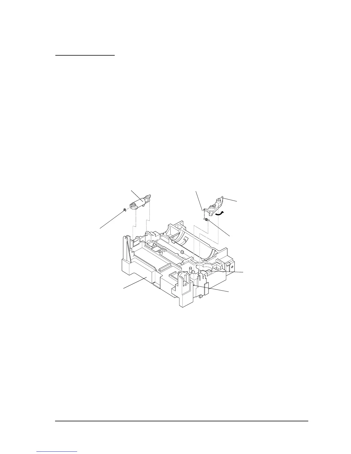
1. Place the ribbon switch lever by fitting its hole onto dowel A of the base frame assembly.
While rotating the ribbon switch lever, make sure that the protrusion part does not catch and
moves freely.
2. Hook the ribbon release spring to the notch of the ribbon switch lever and hook B of the base
frame assembly.
3. Fit the holes of the ribbon release lever to 2 shafts of the base frame assembly; then secure it
with the RE.
✓ Check that the ribbon switch lever and ribbon release lever are attached in the proper
directions.
4. Attach the ribbon intermediate gear to the base frame assembly.
5. Attach the ribbon transmission gear and ribbon take-up assembly together to the base frame
assembly.
Ribbon switch lever
Notch
Ribbon release lever
RE (3)
Ribbon release spring
Base frame assembly
A
B

 Loading...


