Rev. A Mechanism Configuration and Operating Principles 2-29
TM-U200 Series (Type A/AM)Technical Manual
Confidential
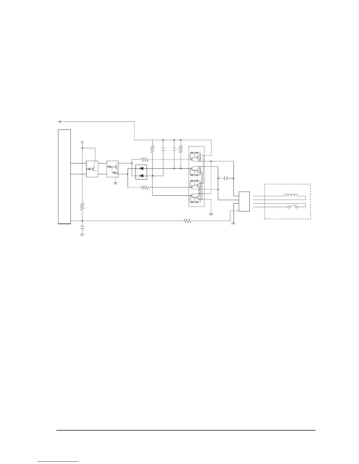
Auto-cutter driver circuit
Rotating the DC motor counterclockwise or clockwise causes the auto-cutter to execute a full cut
or a partial cut (one point left uncut). The driver IC (U6) has a full-bridge configuration and
controls motor rotation, clockwise and counterclockwise.
The position of the auto-cutter blade is detected by the signal connected to P67 of the CPU.
Figure 2-29 Auto-cutter drive circuit
1
2
3
CN9
4
AC M1
AC M2
GND
AC RES
12
C21
R35
R106
R34
P100
P101
1
2
4
3
14
NEC
+24A
+24A
3
4
P67/AN7
C20
C106
U5
10
7
5
9
3
1
6
4
2
8
R107
C107
DM129
QM108
4
3
1
2
1
4
5
23
QM108
1
4
5
23
+5V
Auto cutter

 Loading...


