Rev. A Disassembly, Assembly, and Adjustment 5-49
TM-U200 Series (Type A/AM) Technical Manual
Confidential
Main Assembly 9 (Case Unit)
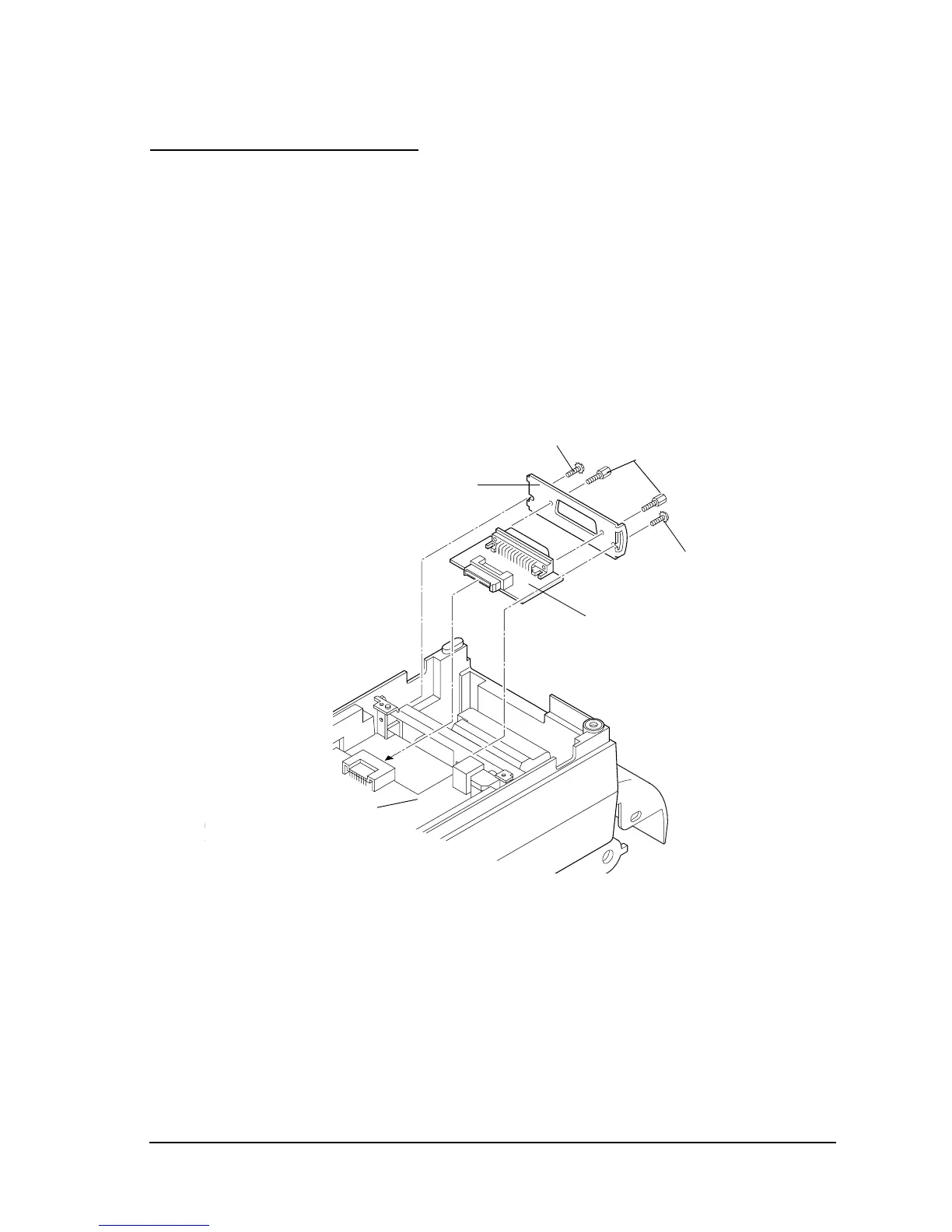
Interface circuit board assembly and connector plate
1. Turn over the printer.
2. Attach the connector plate to the interface circuit board assembly and secure with the
hexagon lock screws (serial interface) or the CPS-tite screws (parallel interface).
3. Connect the interface circuit board assembly to the main circuit board assembly and secure
with the screws
Serial Interface.
Hexagon
lock screws
[0.39 to 0.59 N • m
(4 to 6 kgf • cm)]
CP(0) (M3x6)
[0.59 to 0.78 N • m
(6 to 8 kgf • cm)]
CP(0) (M3x6)
[0.59 to 0.78 N • m
(6 to 8 kgf • cm)]
Connector plate
Interface circuit
board assembly
Main circuit board assembly

 Loading...


