Rev. A Mechanism Configuration and Operating Principles 2-19
TM-U200 Series (Type A/AM)Technical Manual
Confidential
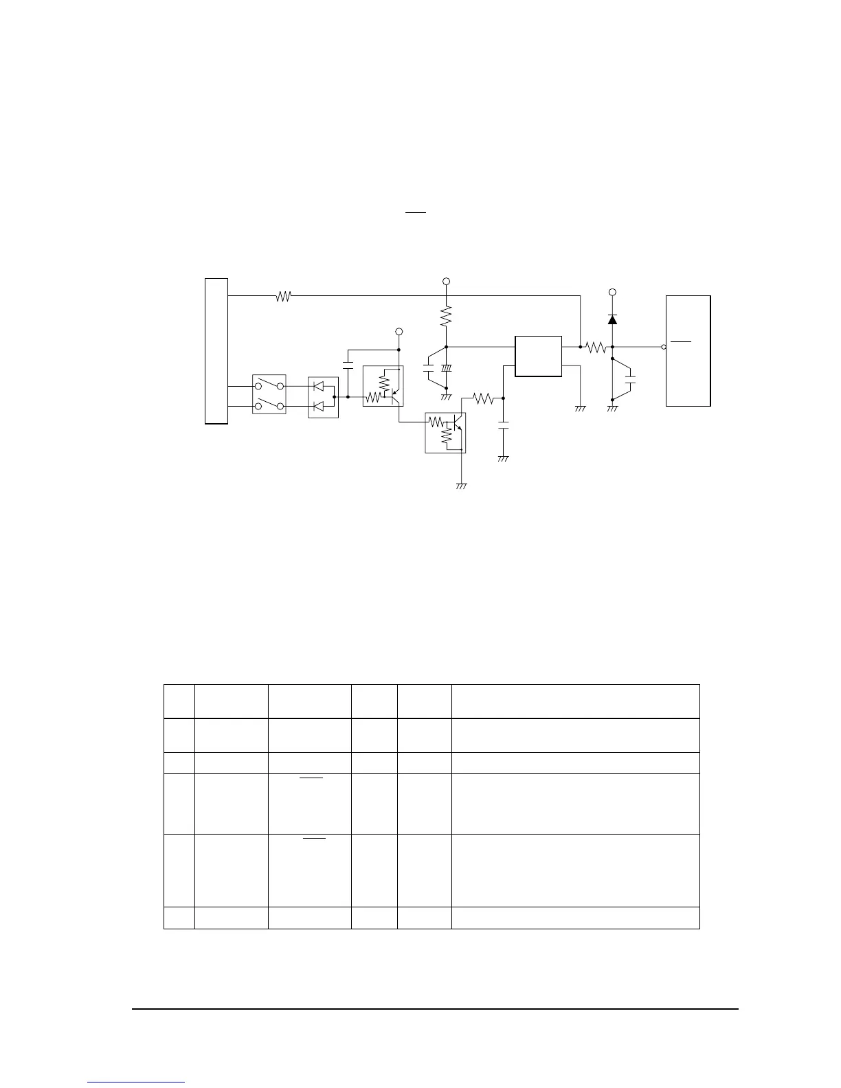
The reset signals differ, depending on the interface specifications:
RS-232 serial interface:Two signals can be selected (DSR signal or pin 25 input signal).
IEEE 1284 parallel interface: Pin 25 must be used for the RESET signal. DIP switch 2-8 is fixed
to ON. The printer can be reset with the Init
signal (pin 31) from
the host.
Figure 2-21 Reset circuit
Pin 29 of CN4 is the reset signal of the IEEE 1284 parallel interface circuit board.
CPU
The printer uses an external 8-bit and internal 16-bit CPU, with an external clock of 14.7 MHz.
The CPU (U5) controls the internal processing of the printer according to the printer control
program written in EPROM (U8) or Flash memory (U101).
CPU pin functions
Pin
No.
CPU
Function Signal Name I/O Level Description
1 P57 ELED/DSW9 I/O TTL ERROR LED. LOW: on. DIP SW 2-1 is read when
P100, P101 are LOW.
2 NMI NMI I TTL Not used (connected to +5 V directly).
3P100 AC1/DSEL
O TTL Auto cutter drive (1) and DIP SW read selection.
LOW: read (read once after initialization).
HIGH: break status when used as motor control
port.
4P101 AC 2/DSEL
O TTL Auto cutter drive (2) and DIP SW read selection.
LOW: read (read once after initialization).
HIGH: break status when used as motor control
port. This pin must change at the same time as
P100.
5 AVCC AVCC I (+5 V) Analog/digital converter standard voltage.
DSR_RESET
#25_RESET
CN4
27
28
8
7
R50
R26
{5 V
+
C28
C101
_
C26
DSW2
Q31
Q32
{5 V
R49
6
4
7
5
IN OUT
C GND
U9
DM111
29
C42
#RST
C27
{5 V
D26
R44
21
RESET
U5

 Loading...


