Rev. A Features and General Specifications 1-15
TM-U200 Series (Type A/AM) Technical Manual
Confidential
Drawer Kick-Out Connector
A pulse specified by the
ESC p
command is output to the drawer kick-out connector. The host
can confirm the status of the input signal by using the
GS a
,
GS r
, or
DLE EOT
commands.
Drawer open/closed signal
The host computer can check the drawer open/closed status with the
DLE EOT
,
GS a
, and
GS r
commands.
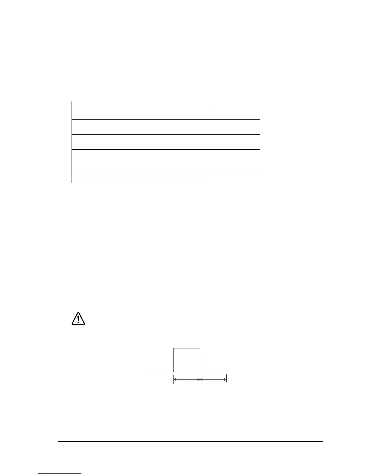
Drawer kick-out drive signal
CAUTION:
To avoid overcurrent, resistance of the drawer kick-out solenoid must be 24
Ω
or more.
Figure 1-9 Drawer kick-out drive signal output waveform
Drawer kick-out connector pin assignments
Pin Number Signal name Direction
1Frame GND —
2 Drawer kick-out drive signal 1
(See "Drawer kick-out drive signal," below.)
Output
3 Drawer open/close signal
(See "Drawer open/closed signal," below.)
Input
4 +24 VDC —
5 Drawer kick-out drive signal 2
(See "Drawer kick-out drive signal," below.)
Output
6Signal GND —
Input signal level: LOW = 0 V
HIGH = 2 to 5 V (at connector pin 3)
Output signal: Voltage = Approximately 24 VDC
Current = 1 A or less
Output waveform: Outputs the waveforms in Figure 1-9 to pins
2 and 5 of the connector. t1 (ON time) and t2
(OFF time) are specified by
ESC p
.
t1 x 2 ms
t2 x 2 ms

 Loading...


