2-14 Mechanism Configuration and Operating Principles Rev. A
Confidential
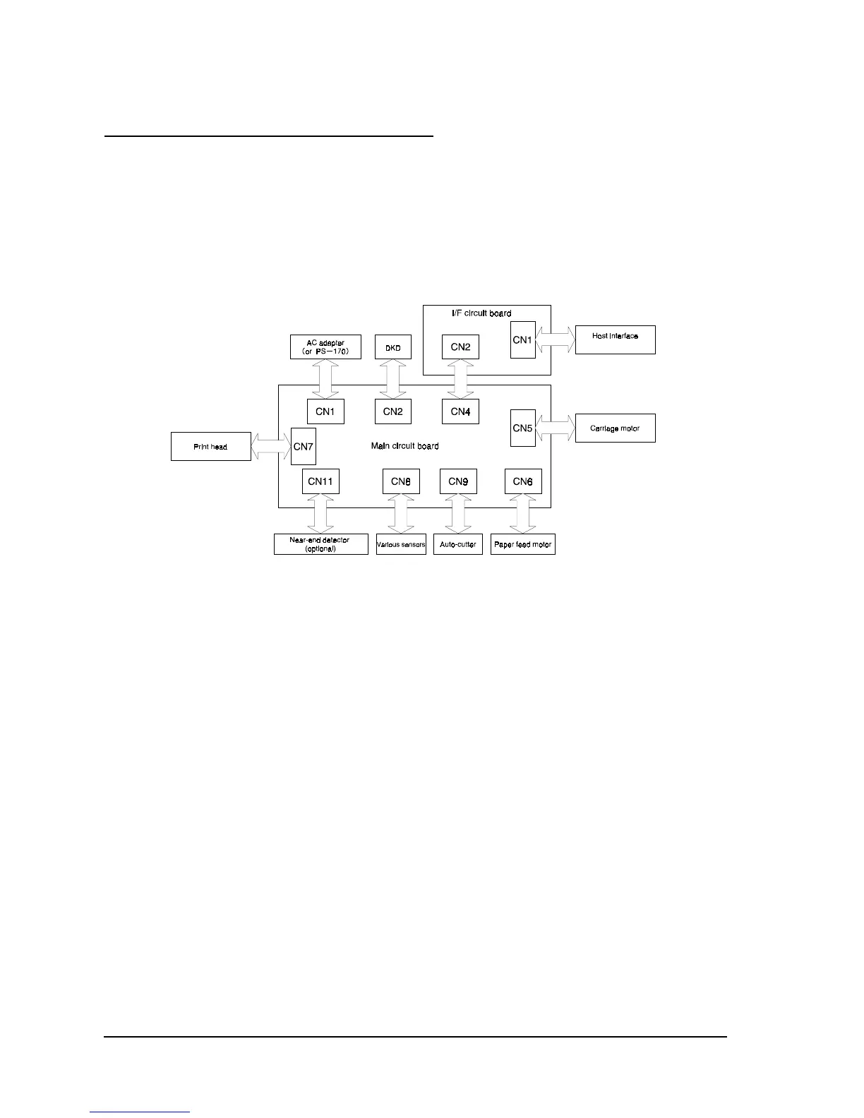
Electrical Circuitry Operating Principles
Hardware Configuration
Component connection diagram
The electrical circuitry of the printer consists of the main circuit board and the interface circuit
boards (UB-S01/RS-232, UB-P01/1284, UB-P02/1284 or UB-S02/RS-485). The figure below is a
component connection diagram for the electrical circuitry.
Figure 2-17 Component connection diagram
Circuit board block diagram
The main circuit board unit contains the following electrical circuits:
❏ Power supply circuit
❏ Reset circuit
❏ CPU [internal RAM: 16K bits (2K x 8 bits)]
❏ Memory [EPROM: 512K bits (64K x 8 bits)]
❏ Operation panel control circuit
❏ Drawer kick-out driver circuit
❏ Print head driver circuit
❏ Paper feed motor driver circuit
❏ DIP switch read circuit
❏ Various detector circuits

 Loading...


