Rev. A Disassembly, Assembly, and Adjustment 5-37
TM-U200 Series (Type A/AM) Technical Manual
Confidential
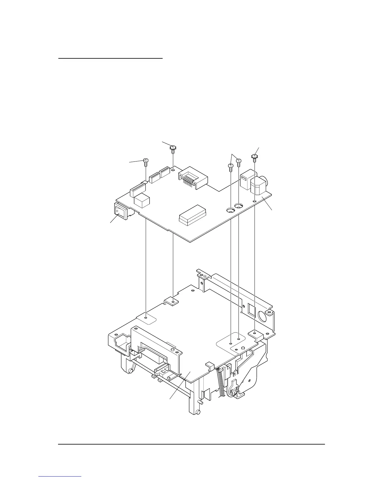
Main Assembly 3 (Case Unit)
Main circuit board assembly
1. Attach the main circuit board assembly to the upper plate by attaching the power switch
side first and then the drawer kick-out and power connectors side. Secure the circuit board
with the screws.
✓ Make sure to use the correct screw for each location.
CP(0)(M3x6)
[0.59 to 0.78 N • m
(6 to 8 kgf • cm)]
CPS-tite (M3x6)
Main circuit
board assembly

 Loading...


