2-18 Mechanism Configuration and Operating Principles Rev. A
Confidential
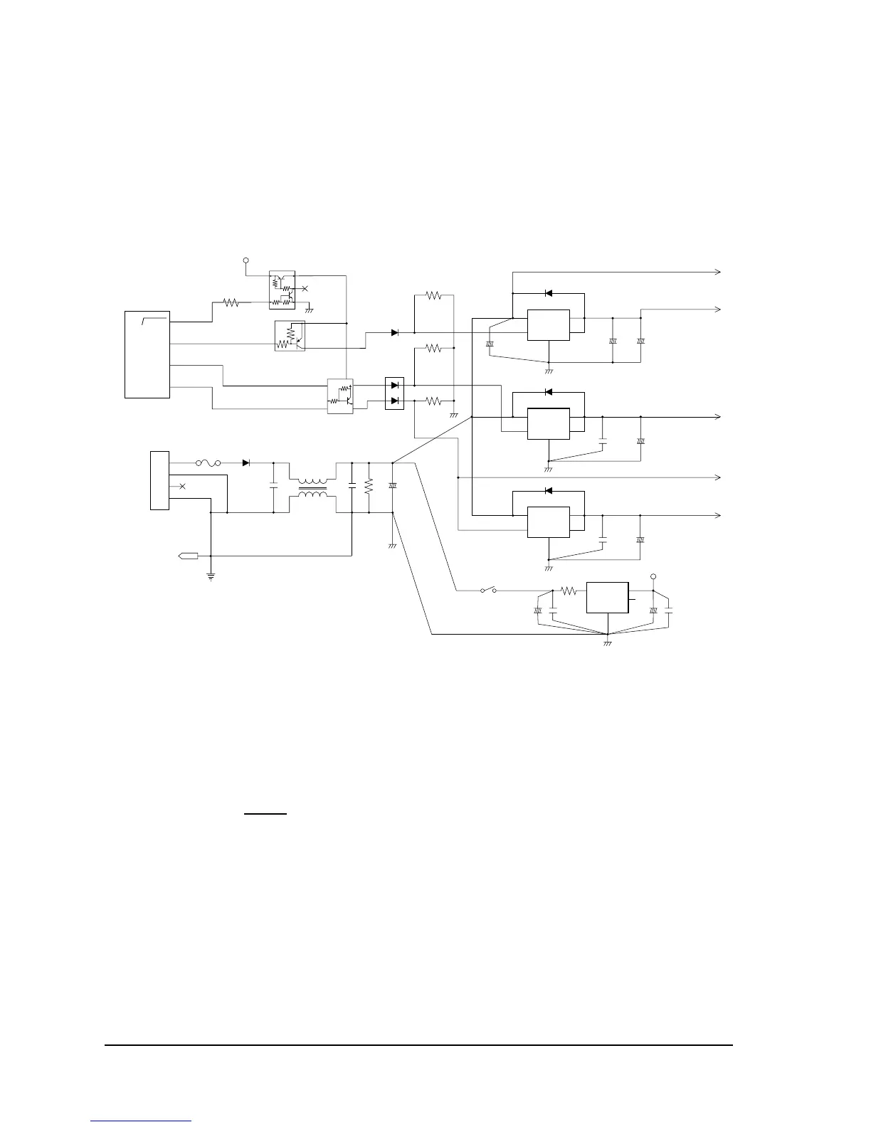
+5 VDC control circuit
The +5 V regulator circuit switches the +24 V power input and converts it to +5 V. The switching
regulator IC (U1) switches the +24 V input, smooths it via C1, and outputs +5 V. Power for the
RS-232 is generated by the internal charge-up circuit on the RS-232 interface driver.
Figure 2-20 Power supply circuit diagram
Control Circuitry
Reset circuit
The reset circuit is used to prevent the CPU from operating erratically and the print head from
printing unexpectedly during the period of unstable voltage immediately after power is turned
on. To accomplish this, the OUT terminal output (pin 6) of the reset IC (U9) is supplied to the
CPU (U5) as the RESET
input signal (pin 21).
The reset IC (U9) monitors the +5 V voltage. When the voltage is 4.5 V or more, reset is released
for the CPU and other components, and the printer becomes ready.
In addition, the C terminal (pin 5) of the reset IC (U9) is connected to the reset signal (DSR signal
or pin 25 input signal) from the host interface via DIP switches 2-7 and 2-8. If a reset signal is
applied to this pin, reset IC output goes LOW and the CPU and other components are reset.
Power switch
D47
Q1
DM128
R5
R6
R7
U2
VIN
53
4
1
SENSW
2
VOUT
D4
U3
G
N
D
VIN
53
4
1
SEN
SW
2
VOUT
D3
U4
G
N
D
VIN
53
4
1
SEN
SW
2
VOUT
D5
+
C14
_
+
C45
_
+
C16
_
+
C7
_
+
C9
_
C6
C8
C12
L1
C11
R17
+
C10
_
F1
U1
G
IN
10 1
6
5
LIN
OUT
+
C2
_
C3
C1
+
C5
_
R114
{5 V
F . G
CN1
1
2
3
4
1
2
3
SH
30 WDTOUT
73 +24COM SW
74 CRCOM SW
P80 WDTOUT
P51/T04
P52/T05
U5
76 PFCOM SW
P53/INT1/TI4
+30V
GND
N . C
F . G
G
N
D
+24DT
HEAD COM
A / C COM
DKD COM
GND
CR COM
nPFCOM
nPFCOM
PF COM
21
SW1
+5I
+24DT
D6
GND
BETA
P.G
+24A
+24DT
+24B
+24C
1
4
1
2
5
3
QM110
5
2
1
4
3
QM115
{5 V
R59
Power switch

 Loading...


