1-14 Features and General Specifications Rev. A
Confidential
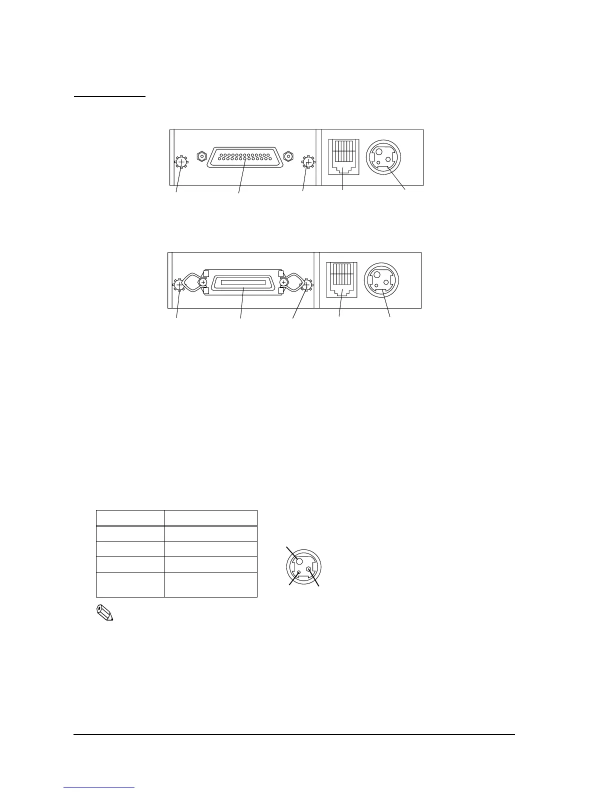
Connectors
Figure 1-7 Connector panel (serial interface)
Figure 1-8 Connector panel (parallel interface)
Interface Connector
See the interface section.
Power Supply Connector
This connector is used to connect the printer to an external power source.
Note:
Be sure to ground the frame ground (FG) screw on the board at the bottom of the unit. Ground wire
terminal hole diameter: 3.2 mm (.13"). Ground wire thickness: AWG 18 or equivalent.
Pin assignments: See the table below.
Power supply connector pin assignments
Pin Number Signal Name
1 + power supply
2GND
3NC
Shell Frame GND
Frame ground
screw
connector
Power supply
Drawer kick-out
connector
Interface
connector
Frame ground
screw
Power supply
connector
Drawer kick-out
connector
Frame ground
screw
Interface
connector
Frame ground
screw

 Loading...


