2-20 Mechanism Configuration and Operating Principles Rev. A
Confidential
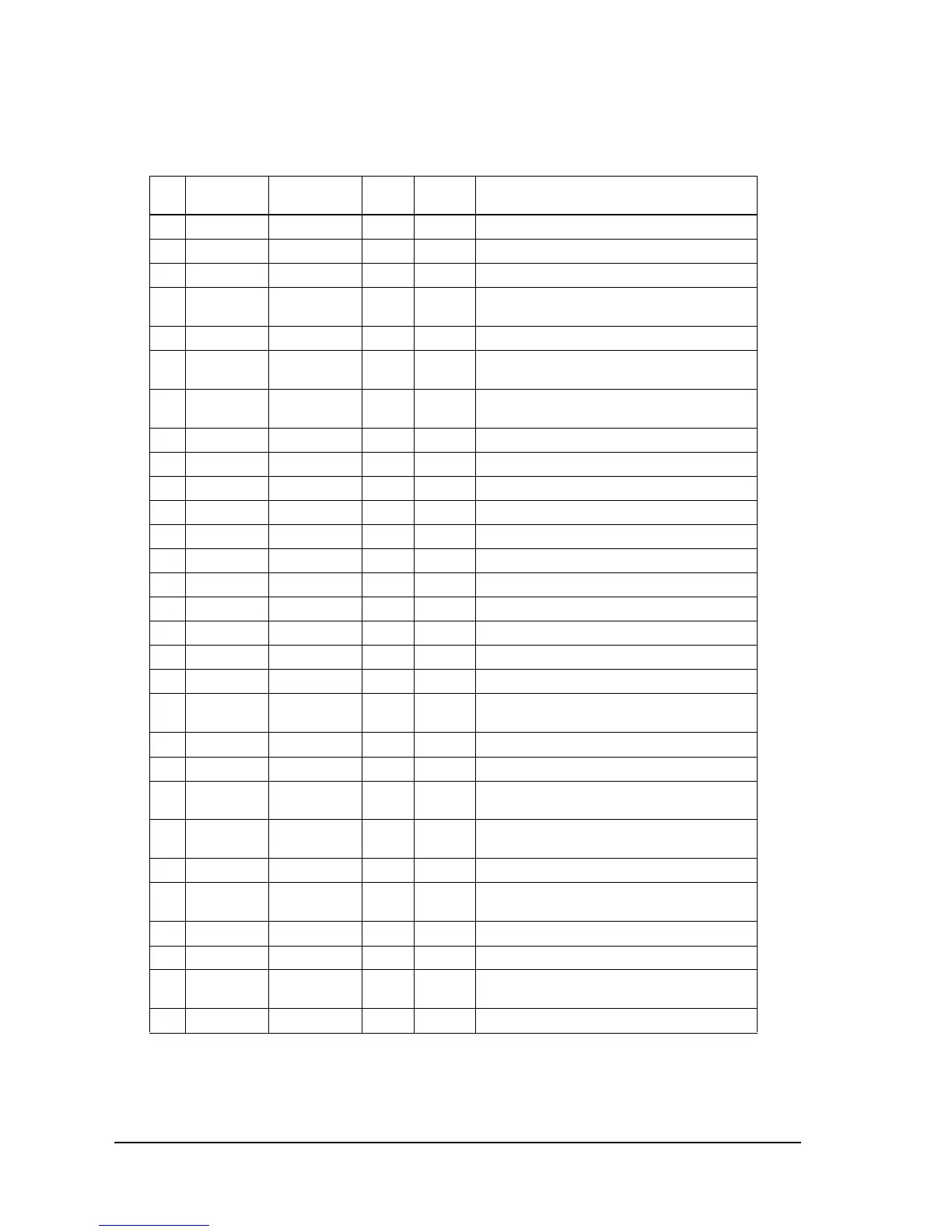
6 AVSS AVSS I (0 V) Analog/digital converter GND terminal.
7 P60/AN0 V DTC I Analog +24 V power voltage detection.
8 P61/AN1 HD TEMP I Analog Head temperature detection.
9 P62 NE I TTL Paper roll near-end detection.
LOW: no paper; HIGH: paper present.
10 P63 DK S I TTL Drawer open/closed. LOW: open.
11 P64 RE I TTL Paper roll end detection.
LOW: paper present; HIGH: no paper.
12 P65 HP DTC I TTL Carriage home position sensor.
LOW: home position.
13 P66 DET I TTL Host interface DET.
14 P67 AC RST I TTL Auto cutter position detection (reset).
15 VCC VCC I (+5 V) Main power terminal.
16 P70 RTS O TTL Host interface RTS. LOW: on.
17 P71 CCE O TTL EP ROM/Flash ROM CE signal. LOW: active.
18 P72/RXD1 RD I TTL Host interface RD. LOW: on.
19 P73/CLK1 CLK IN/DTR I/O TTL Host interface CLK IN/DTR.
20 P74/TXD1 SD O TTL Host interface SD. LOW: on.
21 RESET RESET I --- CPU reset input. LOW: on.
22 CLK CLK O TTL Not used. Open.
23 VSS VSS I (0 V) GND terminal.
24 X1 X1 I --- Connected to ceramic vibration generator.
f=14.74 MHz ± 0.5%.
25 X2 X2 O --- Connected to ceramic. f=14.74 MHz ± 0.5%.
26 EA EA I TTL External memory access. Fixed to LOW.
27 P75 A16/DSW11 O TTL External memory address A16 (software)/DIP
switch 2-5 read (when P100 and P101 are LOW).
28 P76 A17/DSW12 O TTL External memory address A17 (software)/DIP
switch 2-6 read (when P100 and P101 are LOW).
29 P77 A18/BTDET O TTL External memory address A18 (software).
30 P80 WDTOUT O TTL Watch dog timer error (and hardware limited
time power supply switch). LOW: error (reset).
31 P81/INT0 CLK IN I TTL Connected to pin #19.
32 P82 PF SW I TTL Paper feed switch. LOW: active.
33 ALE ALE O TTL Address latch enable signal. Latches address
on bus AD0 to AD7 at fall.
34 VCC VCC I (+5 V) Main power terminal (+5 V).
CPU pin functions
Pin
No.
CPU
Function Signal Name I/O Level Description

 Loading...


