Rev. A Mechanism Configuration and Operating Principles 2-21
TM-U200 Series (Type A/AM)Technical Manual
Confidential
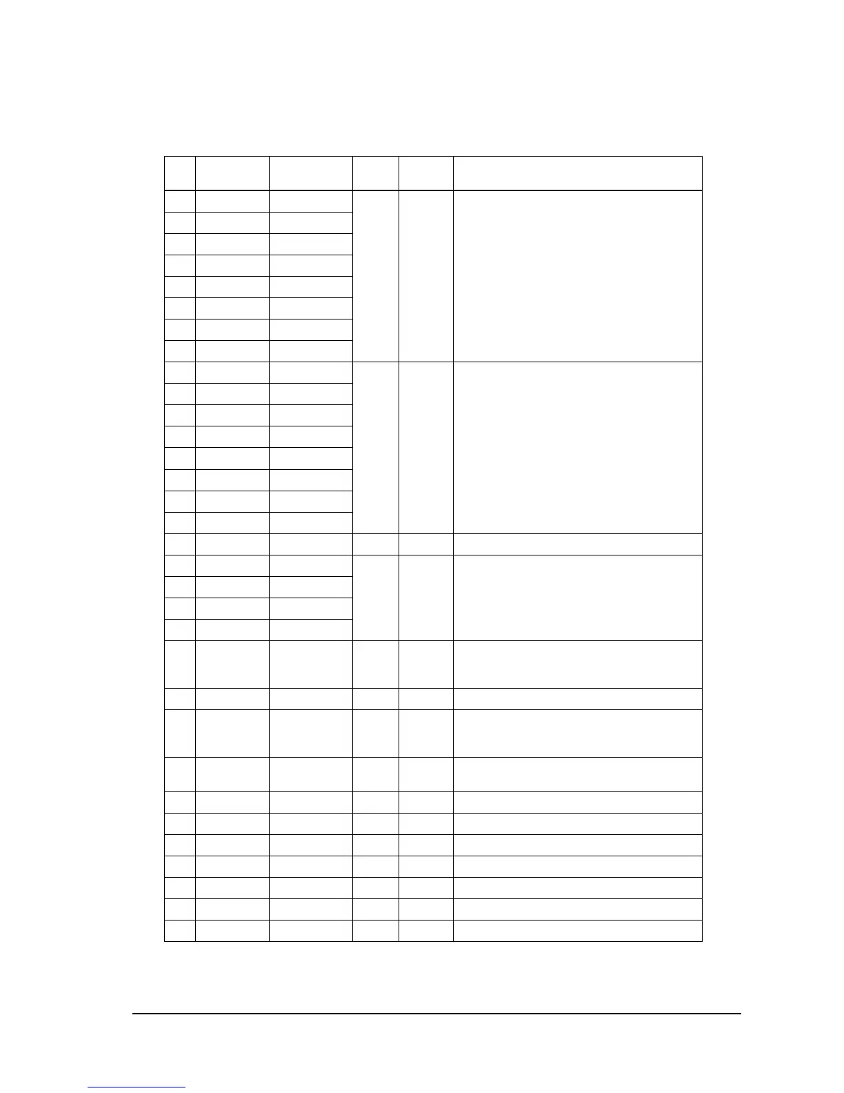
35 AD0 AD0 3-state TTL Address/data bus.
Transmits address (lower 8 bits) and data.
36 AD1 AD1
37 AD2 AD2
38 AD3 AD3
39 AD4 AD4
40 AD5 AD5
41 AD6 AD6
42 AD7 AD7
43 A8 A8 O TTL Address bus (address upper 8 bits).
44 A9 A9
45 A10 A10
46 A11 A11
47 A12 A12
48 A13 A13
49 A14 A14
50 A15 A15
51 VSS VSS I (0 V) GND terminal.
52 P20 CR A/DSW1 I/O TTL Carriage motor driver control 2-2 phase
excitation. All terminals on (LOW): hold.
DIP SW 1-1 to 1-4 read when P100 and P101 are
LOW.
53 P21 CR B/DSW2
54 P22 CR C/DSW3
55 P23 CR D/DSW4
56 P90 PF A/DSE5 I/O TTL Paper feed motor driver control 2-2 phase
excitation. All terminals on (LOW): hold. DIP SW
1-5 read when P100 and P101 are LOW.
57 P91 RES/DSW6 I/O TTL DIP SW 1-6 read when P100 and P101 are LOW.
58 P92 PF C/DSW7 I/O TTL Paper feed motor driver control 2-2 phase
excitation. All terminals on (LOW): hold. DIP SW
1-7 read when P100 and P101 are LOW.
59 P93 A19/DSW8 I/O TTL External memory address A19 (software)/DIP
SW 1-8 read when P100 and P101 are LOW.
60 RD RD O TTL External memory data read signal.
61 WR WR O TTL External memory data write signal.
62 P32 DKD1 O TTL Drawer kick-out driver signal 1. LOW: active.
63 P33 DKD2 O TTL Drawer kick-out driver signal 2. LOW: active.
64 P40 HEAD8 O TTL Print head #8 driver signal. LOW: on.
65 P41 HEAD7 O TTL Print head #7 driver signal. LOW: on.
66 P42 HEAD6 O TTL Print head #6 driver signal. LOW: on.
CPU pin functions
Pin
No.
CPU
Function Signal Name I/O Level Description

 Loading...


