2-22 Mechanism Configuration and Operating Principles Rev. A
Confidential
ROM (512K bit) or FLASH MEMORY (4M bits or 8M bits)
The printer control program and the character generator data are written in ROM (U8) or Flash
memory (U101). The control program controls the basic operations of the printer. All CPU (U5)
operations follow this program.
RAM (CPU internal 2KB)
RAM is used as temporary storage for the following:
❏ Data received from the interface (receive buffer)
❏ Pattern data to be printed by the print head (printer buffer)
❏ Data used by the CPU (U5) during processing (flags, pointers, etc.).
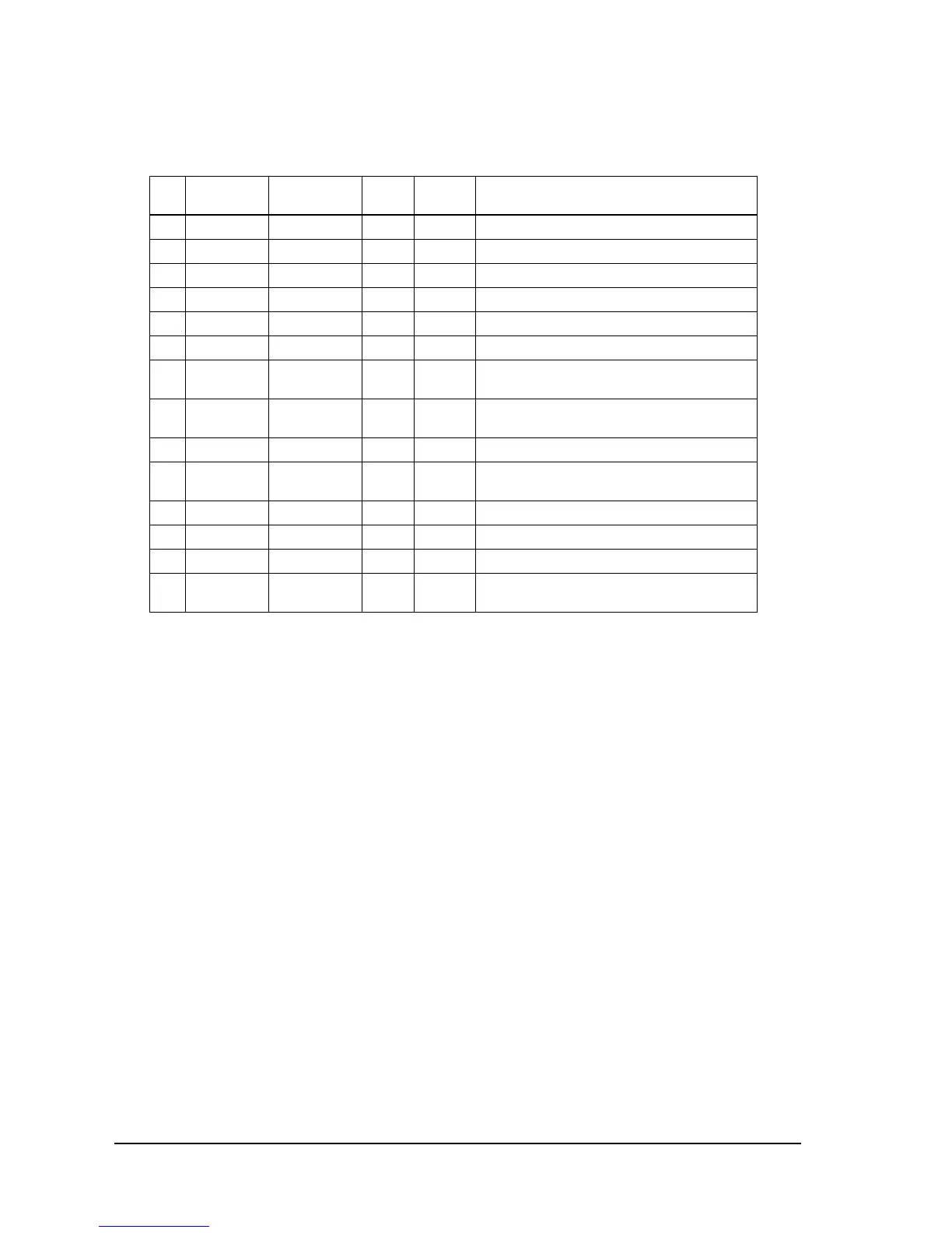
67 P43 HEAD5 O TTL Print head #5 driver signal. LOW: on.
68 P44 HEAD4 O TTL Print head #4 driver signal. LOW: on.
69 P45 HEAD3 O TTL Print head #3 driver signal. LOW: on.
70 P46 HEAD2 O TTL Print head #2 driver signal. LOW: on.
71 P47 HEAD1 O TTL Print head #1 driver signal. LOW: on.
72 P48 HEAD9 O TTL Print head #9 driver signal. LOW: on.
73 P51/T04 +24VCOM SW O TTL Head, auto cutter, drawer kick-out power
switch. LOW: drive.
74 P52 CRCOM SW O TTL Carriage motor power switch. LOW: motor
drive.
75 VCC VCC I (+5 V) Main power terminal (+5 V).
76 P53 PFCOM SW O TTL Paper feed motor power switch LOW: motor
drive.
77 P54 CLK REQ O TTL HOST interface CLK REQ.
78 VSS VSS I (0 V) GND terminal.
79 P55 CTS I TTL Host interface CTS. LOW: on.
80 P56 PLED/DSW0 I/O TTL PAPER OUT LED. Low: on.
DIP SW 2-2 read when P100 is LOW.
CPU pin functions
Pin
No.
CPU
Function Signal Name I/O Level Description

 Loading...


