Rev. A Mechanism Configuration and Operating Principles 2-23
TM-U200 Series (Type A/AM)Technical Manual
Confidential
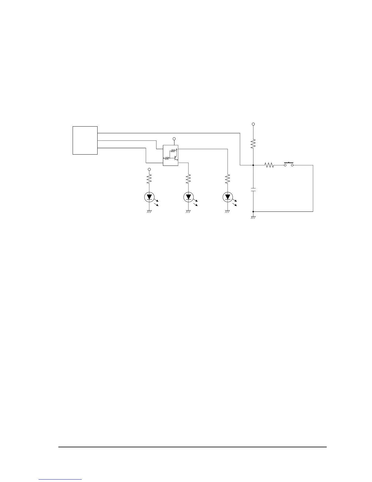
Operation panel
The operation panel is located on the main circuit board and has 3 LEDs (
POWER
,
ERROR
, and
PAPER OUT
) and 1 switch (
FEED
). The
POWER
LED is driven at the same time as +5 V is
supplied by the power supply circuit. The
ERROR
and
PAPER OUT
LEDs are driven by U5.
Switch detection is also executed by the U5.
Figure 2-22 Operation panel circuit
P82
C17
R55 R56
R41
R54
R15
SW2
1 1 1
222
(PAPER)
D12
(ERROR)
D11
(POWER)
D13
U5
32 PF SW
1 ELED/DSW9
80 PLED/DSW0
P57/T03
P56/INT3/TI2
GND
4
1
2
5
3
QM109
+5V
+5V
+5V

 Loading...


