Rev. A Disassembly, Assembly, and Adjustment 5-55
TM-U200 Series (Type A/AM) Technical Manual
Confidential
The amount (A) without the spacers: 6 mm (0.24”)
The value of (A) is obtained by calculation only. Therefore, it may not be appropriate for all
printers.
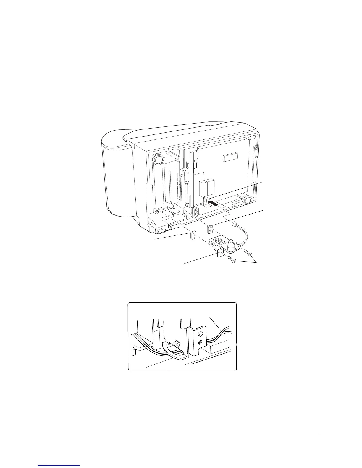
4. Attach the spacers (if desired) and near-end detector assembly to the lower case and secure
them with the screws. Make sure the spacers are positioned in the correct direction, as
shown in the illustration.
5. Insert the near-end detector’s lead wires into the connector.
✓ Make sure to arrange the lead wires as shown in the illustration.
6. The inner diameter of the paper core should be 10.5 to 12.5 mm (0.41 to 0.49”).
✓ After assembling the near-end detector assembly, make sure the near-end detection lever
moves smoothly.
Round corner
Round corner
Near-end detector assembly
CPT-B (M3x12)
of spacer
[0.59 to 0.78 N • m
(6 to 8 kgf • cm)]
Connector CN11
Near-end detector’s
lead wires

 Loading...


