Rev. A Features and General Specifications 1-21
TM-U200 Series (Type A/AM) Technical Manual
Confidential
bidirectional. Both modes fail to proceed concurrently in compatibility mode, causing half
duplex transmission. The IEEE 1284 nibble/byte modes are under development in draft form
and may be subject to change.
Interface Connector Pin Assignments
Notes:
❏
Overscored signal names are LOW active signals.
❏
If a host does not provide for the signal lines listed above, two-way communication fails.
❏
For interfacing, signal lines must use twisted pair cables with the return sides connected to signal
ground level.
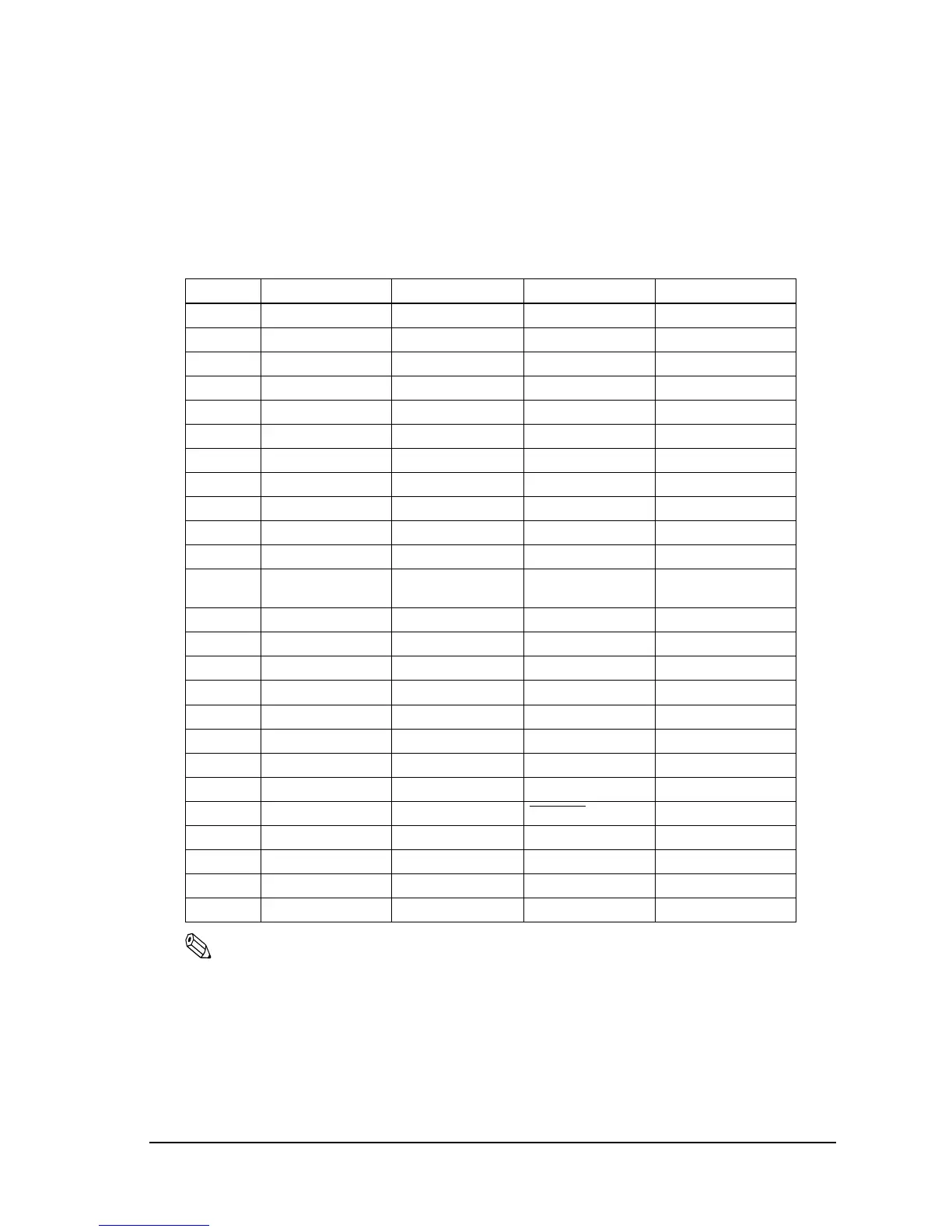
IEEE 1284 interface connector pin assignments and functions
Pin number Source Compatibility Mode Nibble Mode Byte Mode
1 Host Strobe Host Clk Host Clk
2 Host/Ptr Data0 (LSB) Data0 (LSB) Data0 (LSB)
3 Host/Ptr Data1 Data1 Data1
4 Host/Ptr Data2 Data2 Data2
5 Host/Ptr Data3 Data3 Data3
6 Host/Ptr Data4 Data4 Data4
7 Host/Ptr Data5 Data5 Data5
8 Host/Ptr Data6 Data6 Data6
9 Host/Ptr Data7 (MSB) Data7 (MSB) Data7 (MSB)
10 Printer Ack PtrClk PtrClk
11 Printer Busy PtrBusy/Data3,7 PtrBusy
12 Printer PError AckDataReq/
Data2,6
AckDataReq
13 Printer Select Xflag/Data1,5 Xflag
14 Hostr AutoFd HostBusy HostBusy
15 NC ND ND
16 GND GND GND
17 FG FG FG
18 Printer Logic-H Logic-H Logic-H
19-30 GND GND GND
31 Host Init Init Init
32 Printer Fault DataAvail
/Data0, 4 DataAvail
33 GND ND ND
34 Printer DK_STATUS ND ND
35 Printer +5V ND ND
36 Host SelectIn 1284-Active 1284-Active

 Loading...


