Rev. A Features and General Specifications 1-25
TM-U200 Series (Type A/AM) Technical Manual
Confidential
Notes:
❏
Do not change the settings of DIP switches 2-2 (fixed to ON) and 2-6 (fixed to OFF).
❏
Changes in DIP switch settings (excluding switches 2-7 and 2-8, which are I/F reset signals) are
recognized only when printer power is turned on or reset using the interface. If the DIP switch setting
is changed after printer power is turned on, the change does not take effect until the printer is turned
on again or reset.
Parallel interface (IEEE 1284)
The DIP switches are located at the bottom of the case. .
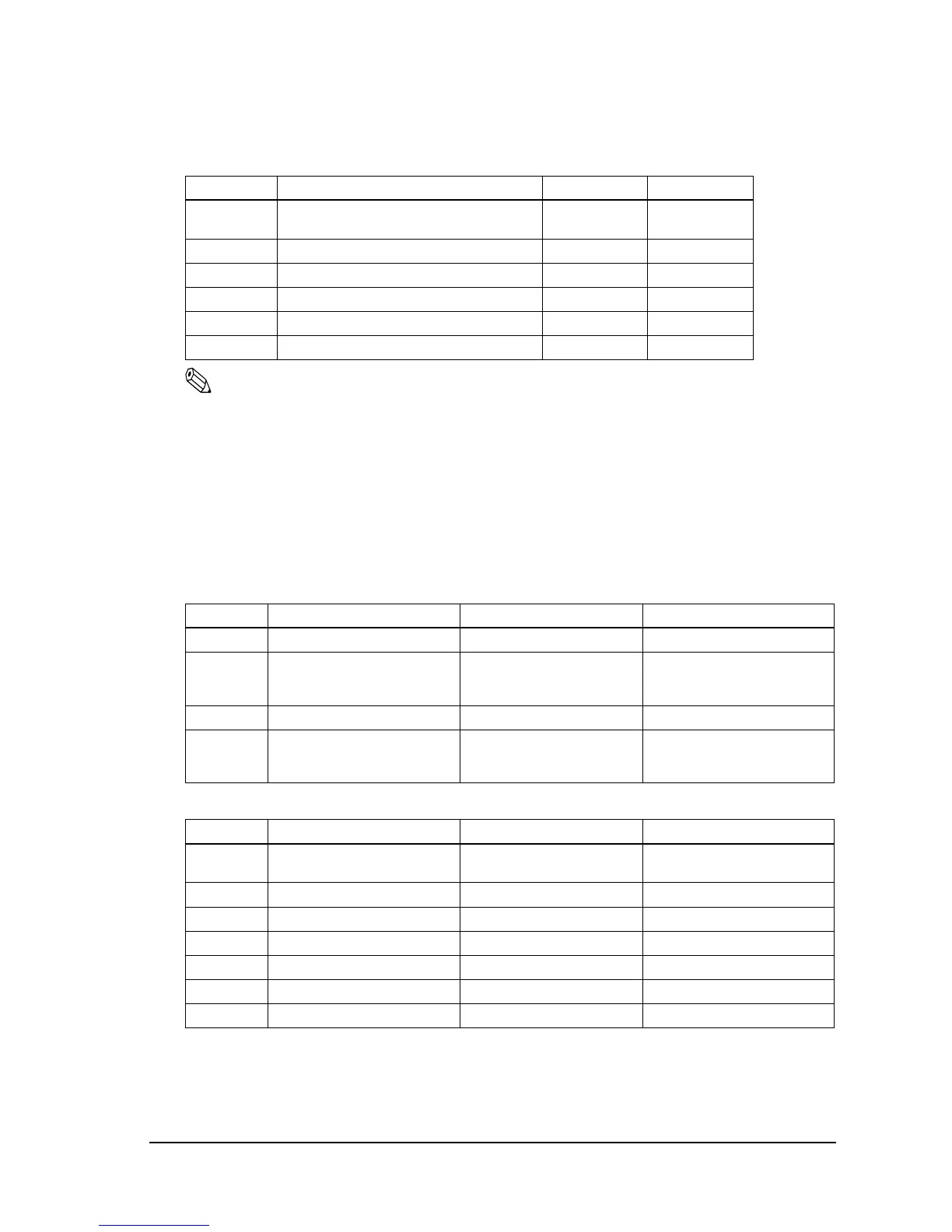
DIP switch 2
DIP Switch Function ON OFF
1 Print column selection
7 ✕ 9 font/9 ✕ 9 font
42CPL/35CPL 40CPL/33CPL
2 For internal use only Fixed to ON.
3 - 5 Undefined
6 For internal use only. Fixed to OFF
7 I/F pin 6 reset signal Enabled Disabled
8 I/F pin 25 reset signal Enabled Disabled
DIP switch 1
DIP Switch Function ON OFF
1 Auto line feed Enabled Disabled
2 Receive buffer 40 bytes Data buffer 1000 bytes (Type A)
Data buffer 512 bytes (Type
AM)
3-7 Undefined
8 Busy condition Receive buffer full
Scanning data
Off-line
Receive buffer full
Scanning data
DIP switch 2
DIP Switch Function ON OFF
1 Print column selection
7 ✕ 9 font/9 ✕ 9 font
42CPL/35CPL 40CPL/33CPL
2 Internal use Fixed to ON
3 Internal use Fixed to OFF
4-5 Undefined
6 Internal use Fixed to OFF
7 Undefined
8 #31 pin reset signal Used Not used

 Loading...


