-- 1 9 --cdte1de1
An output from AP04 activates the start voltage, which is connected in parallel
with the welding voltage by transistor Q14. The start voltage is activated as long
as the HF genarator is active: see AP01:4.
AP01:4 HF Generator
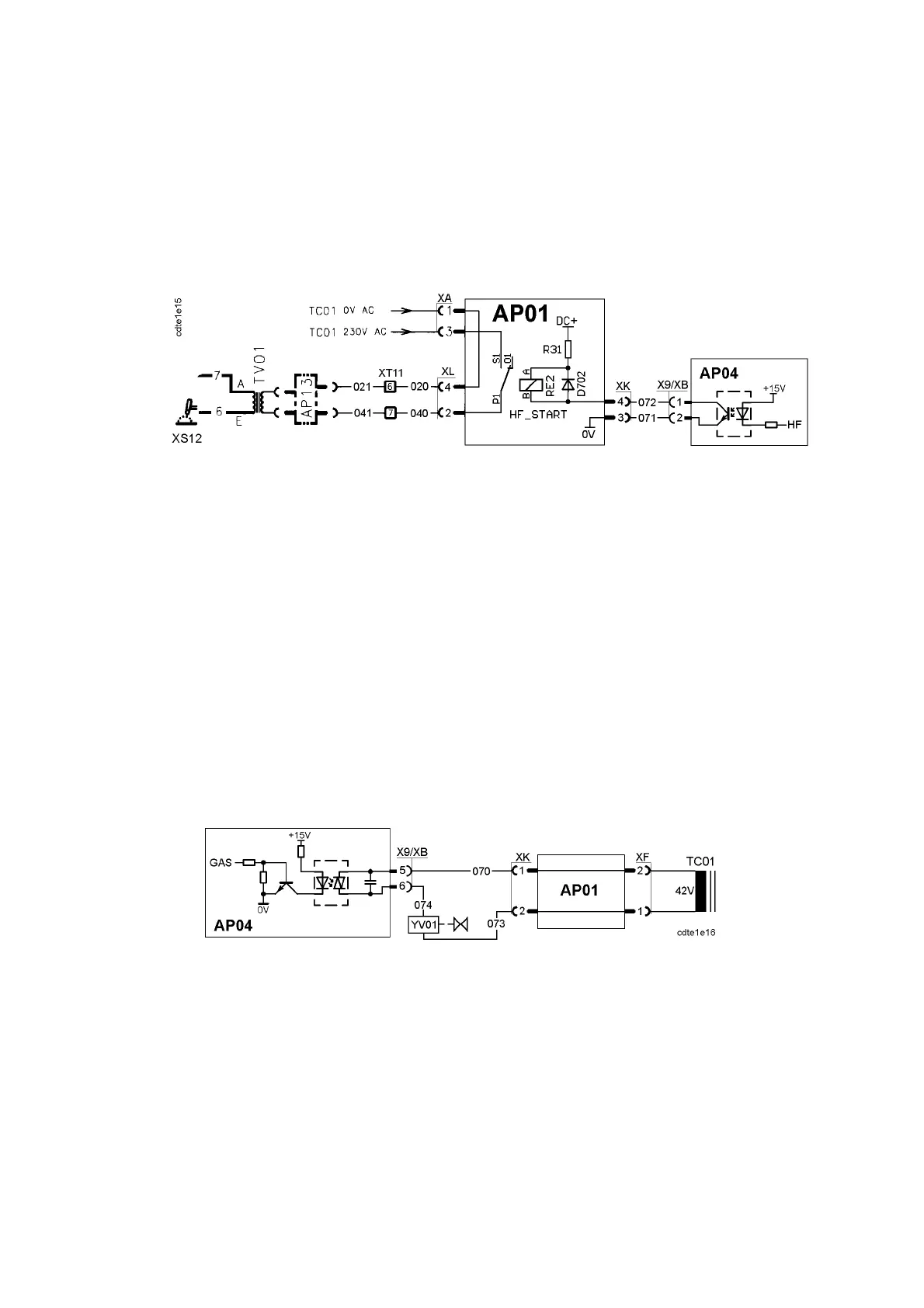
Control circuits for the HF start unit
The HF generator, AP13, is controlled from processor board AP04. It is on only
until an arc is established. If no arc is established, the generator is stopped after
about two seconds.
To check if the HF generator works: Make a short circuit between X9:1 and 2.
Note: Don’t leave the generator on for more than a couple of seconds, otherwise
it might be overheated. Some HF generators have an inbuilt overtemperatur e
protection feature which switches off the generator when it is too hot. When the
generator has cooled down, it can be operated again.
The output voltage from AP13 is about 550V. The voltage at the secondary side
of TV01 is about 7 to 9kV.
AP01:5 Gas valve
Control circuits for the gas valve
The gas valve is controlled from processor board AP04.
Easy test of the gas valve: Make a short circuit between X9:5 and 6.