-- 6 0 --
cdte1de1
Gate pulses to the AC IGBTs
This instruction applies to items 9 and 10 on pages 58--59.
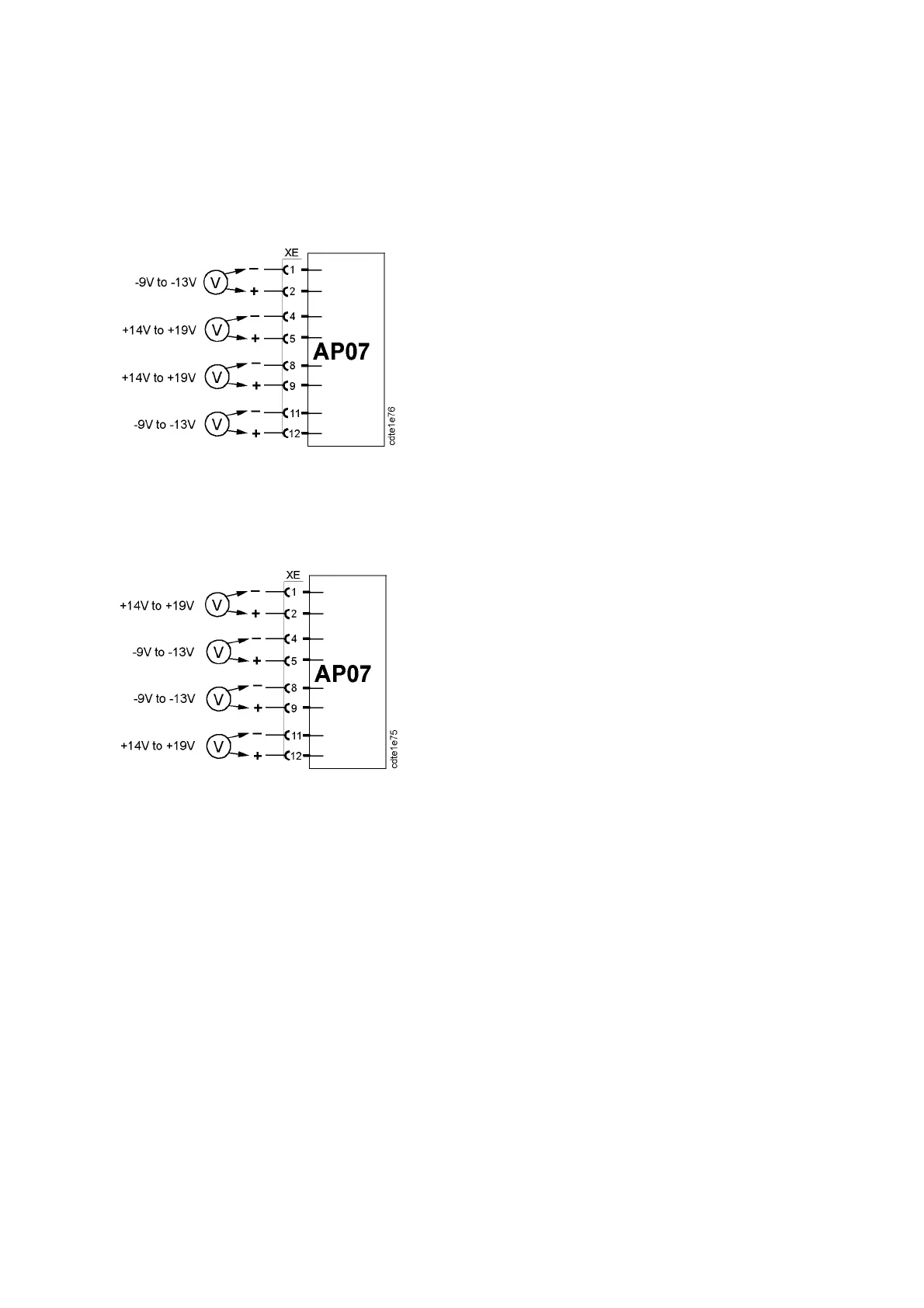
Measure the voltages at connector XE when the selector switch on the test board is in
position 2: TEST ON. Measure as shown in the diagram below.
Gate voltages when electrode (XS13) is positive
Measure the voltages at connector XE when the selector switch on the test board is in
position 3: CHANGED POL. Measure as shown in the diagram below.
Gate voltages when electrode (XS13) is negative
If the voltages are within the tolerance, the gate drive circuits are healthy.
To check the temperature monitoring of the IGBTs: Disconnect connector XB (= temp. sensor
ST02). All measurements above must now show --9V to --13V. The temperature monitor ing is
described on page 47.