-- 5 --cdte1de1
INTRODUCTION
On the DC side, this generation of ESAB inverters for AC/DC welding is based on
fast--switching IGBTs (Insulated Gate Bipolar Transistors). IGBT module Q05 is a half--wave
bridge with integral freewheel diodes.
Low saturation voltage IGBTs are fitted in the AC converter. Q01 -- Q04 are single switch
modules with integral freewheel diodes.
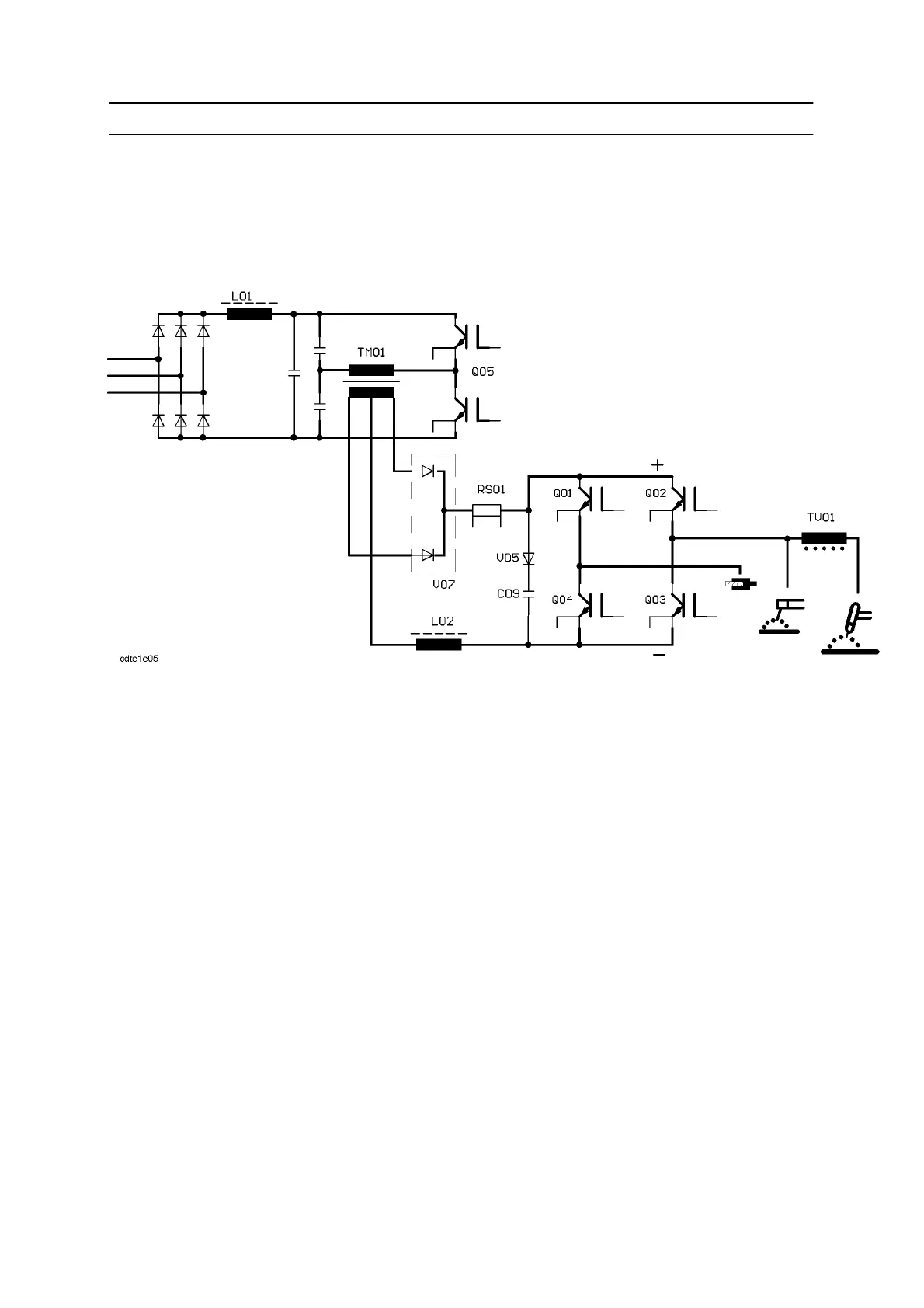
Schematic circuit diagram for the DTE 255
The principle for the DC part is a “Half bridge push pull flow converter”. The nominal 400V
three phase mains supply is rectified and filtered and then centre--tapped.
The AC current through the primary winding of transformer TM01 is controlled by IGBT
module Q05. The output current is controlled by the duration of t he On state of the IGBTs.
(Pulse Width Modulation, PWM)
The frequency is 20 kHz. Only one IGBT is on at the time. The minimum time gap between
On and Off state is 4ms.
The centre tap of the secondary side of transformer TM01 is the negative pole. Inductor L02
smooths the current and stores switching energy. Each end of the secondary winding is
connected to a fast recovery diode module V07. The following shunt RS01 provides the
actual current signal for control purpose.
The AC converter has four single--module IGBTs. If no control signal is applied, all IGBTs
are turned off. No output current is possible.
During normal operation there are control signals in either forward polarity (two IGBTs are
on and two are off) or in reverse polarity.
Just before changing the polarity the set value of the output curr ent is decreased (or
increased), by the process board AP04, to a certain value from which the polarity is changed.
The change of polarity is so fast that the arc does not extinguish, even without using HF
ignition.