-- 2 7 --cdte1de1
AP02 Primary IGBT circuit board
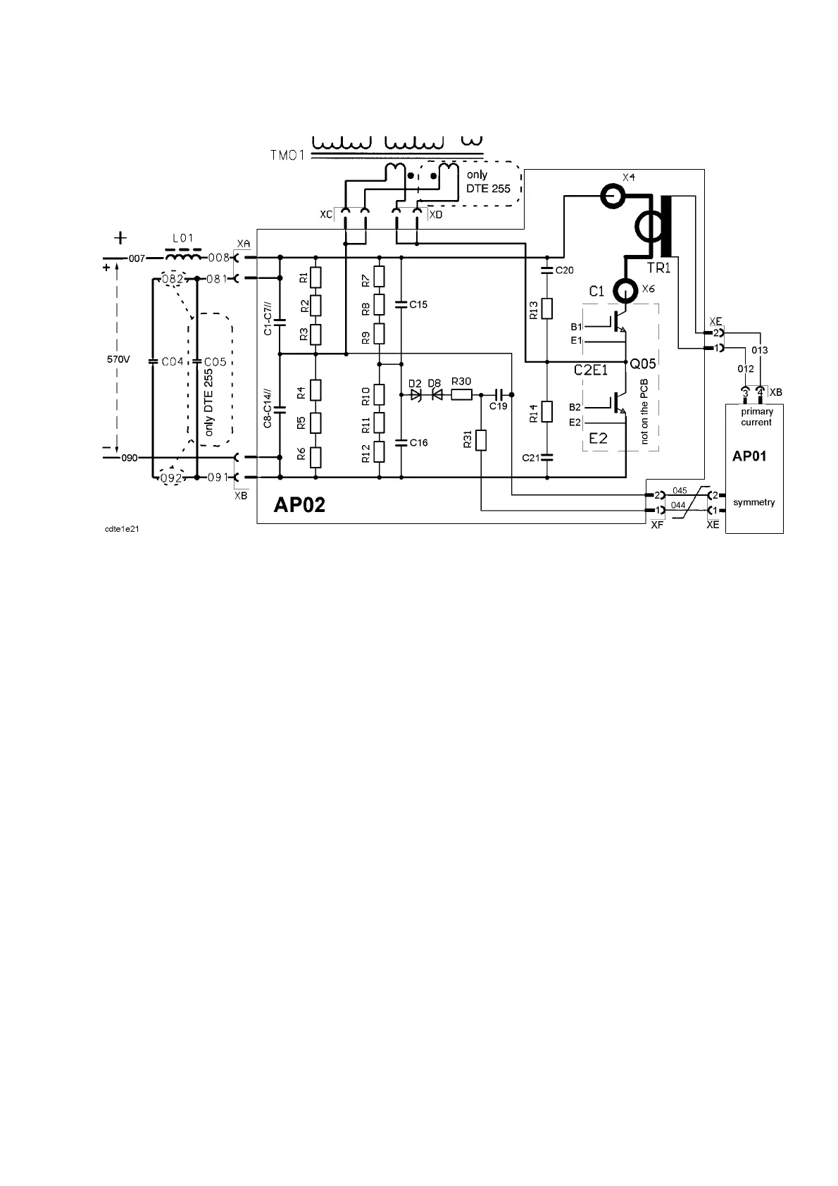
Circuit diagram for AP02
Comments to the diagram above: Capacitor C05 is fitted only in the DTE 255.
In the DTE 200, main transformer TM01 has only one primary winding.
Capacitors C1, C2, C13 and C14 are fitted to circuit board AP02 only in the DTE 255.
Test instructions for the IGBT module are on page 61.
IGBT circuit board AP02 performs the following duties:
S Connecting the main transformer TM01 with the IGBT half--bridge Q05.
Q05 drives an alternating current through the primary side of transformer TM01 by
charging and discharging C1--C7 and C8--C14 at a frequency of 20kHz.
S Creating a signal to maintain the symmetry (avoid saturation) of the main transfor mer.
The voltage difference between a fixed middle point at the anode of diode D2 and a
variable point at connector XF:2 is used as the reference for the symmetry. Unbalanced
operation of the transformer is avoided by blocking the firing cycle of whichever side
which is causing the unbalance. This is carried out by the gate circuits: see page 20.
A window of 62V without any inter action is provided by the zener diodes D2 and D8.
This means that only if the unbalance is more than 62V will the outputs of XF:1 and 2
start to act. This action does not stop the welding.
Note: The polarity of the signal from connector XF is important.
S Generating a primary current signal to protect the machine.
Current transformer TR1 must never be operated with an open--circuit secondary
(= output). This could destroy it by flashover between the windings.
See page 22 for more information on the primary overcurrent protection .